Configuring Input References
Depending on the type of input reference, some of its settings may be user-editable. To access these settings for a given input reference, choose one of the two methods described below.
(To disable references or change the priority that your timing system will be guided by those references, visit Configuring Input Reference Priorities).
Note: The illustrations shown below are examples. The windows displayed in your Web UI may look differently.
How to Configure an Input Reference
To access the user-editable settings of an Input Reference, choose one of these two methods:
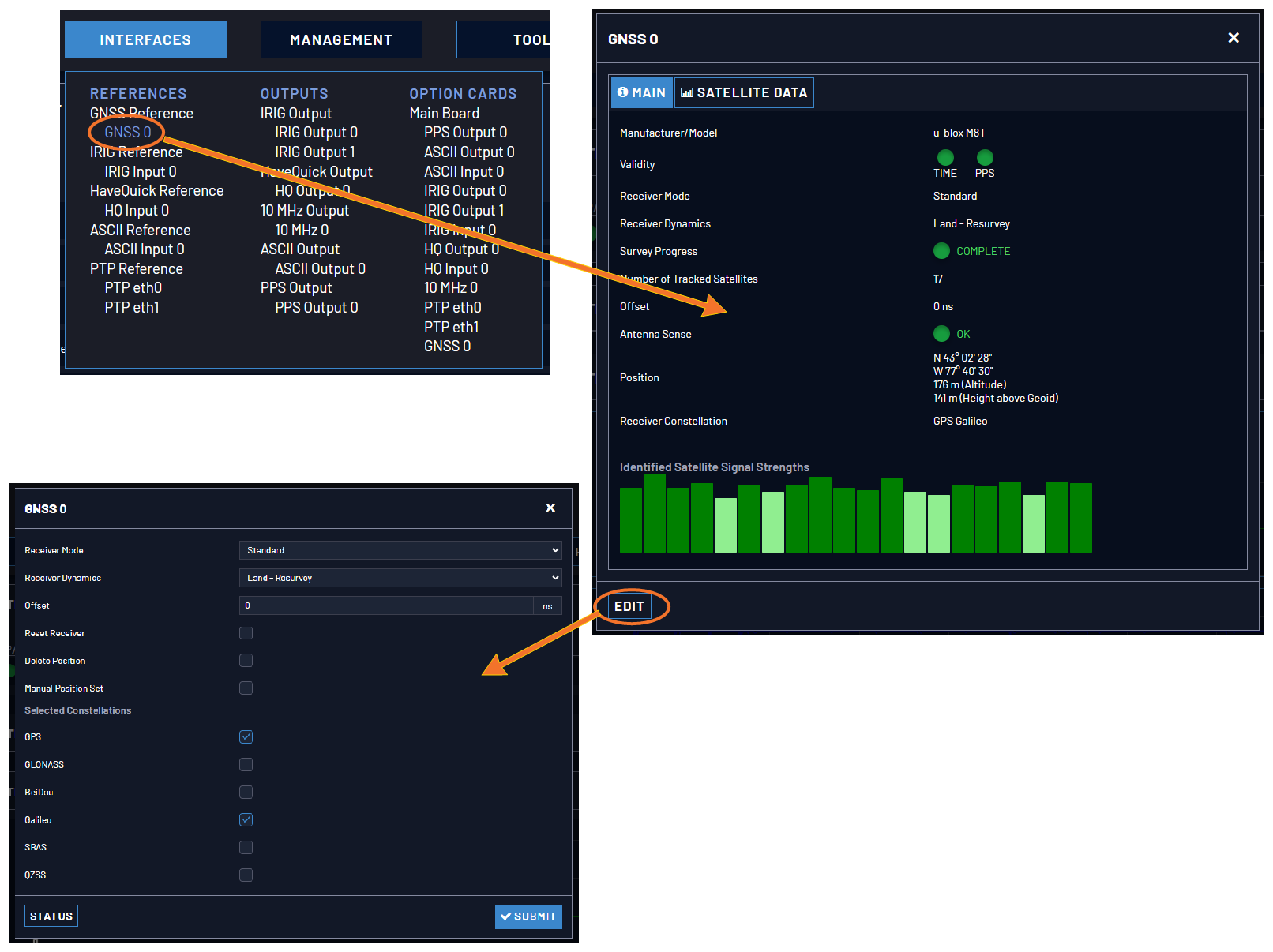
- Under INTERFACES > REFERENCES, click the desired reference.
- The Status window for the specific reference you selected will be displayed. Click the Edit button in the bottom-left corner.
- The settings window for the chosen reference will be displayed. Edit the field(s) as desired.
- In the INTERFACES > REFERENCES drop-down menu, click REFERENCES (white on orange), or an input reference category (e.g., "GNSS reference").
- In the Status window, click the GEAR button next to the desired input reference.
- The settings window for the chosen reference will be displayed. Edit the field(s) as desired.
For more information, see Managing References.
The following configuration instructions apply to optional inputs on the basic unit model. For specifics on inputs made available through option cards, see the section Option Cards.
Configure a 1PPS Input
A 1PPS Input can be set up through the Multi-I/O connector (see Configurable Connectors).
To configure the settings of the PPS Input (also referred to as ‘Reference’), go to its Edit window..
The Web UI list entries for these cards are:
- 1PPS In/Out
- 1PPS In/Out, Fiber
The connector number for the input is: J1
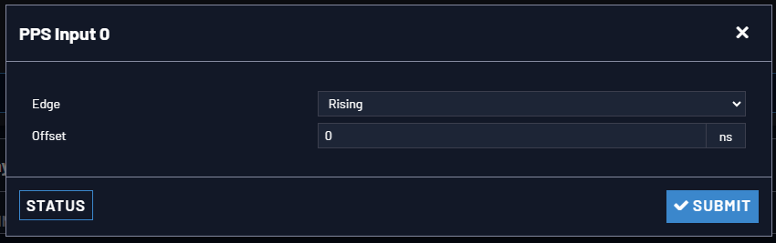
The Edit window allows the configuration of the following settings:
- Edge: The operator can select either the rising or the falling edge as the input time reference (defines the on-time point of the signal).
- Offset: It is possible to add an offset to the input signal (to account for cable delays), with a resolution of 5ns and a positive or negative value of 500 ms maximum.
Configure an ASCII Input
An ASCII Input is available by default configuration through the Multi-I/O connector (see Configurable Connectors).
To configure the ASCII Input (also referred to as ‘Reference’), go to its Edit window.
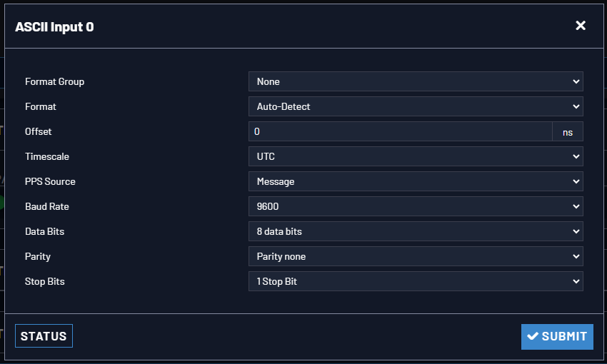
The Input Edit window allows the configuration of the following settings:
- Format Group: Determines the time code message format category (see also Time Code Data Formats.) Choices are:
- Auto
- Spectracom
- NMEA
- ICD-153
- EndRun
- Format: Once a Format Group has been selected, one or more Format fields may appear, allowing you to select one or more time code Formats. For detailed specifications and limitations on the supported time code formats, see Time Code Data Formats.
Note: If Auto is chosen as the format group, the format will automatically be Auto-detect. SecureSync will attempt to identify the format of the incoming ASCII message.
- Offset: Provides the ability to account for ASCII input cable delays or other latencies in the ASCII input. The Offset value is entered and displayed in nanoseconds (ns). The available Offset range is –500 to +500 ms.
- Timescale: Used to select the time base for the incoming ASCII time code data. The entered Timescale is used by the system to convert the time in the incoming ASCII data stream to UTC time for use by the System Time. The available choices are:
- UTC: Coordinated Universal Time ("temps universel coordonné"), also referred to as ZULU time
- TAI: Temps Atomique International
- GPS: The raw GPS time as transmitted by the GNSS satellites (as of <D-M-Y>, this is 18 seconds ahead of UTC time)
- A local clock set up through the Time Management Page: This option will appear under the name of the local clock you have set up. Refer to The Time Management Screen for more information on how to configure and read the System Time. Local timescale allows a Local Clock to apply a time offset for Time Zone and DST correction.
The incoming input time information may be provided as local time, but System Time may be configured as UTC time, so internal computations need to be performed. With the Timescale field set to “Local”, select the name of a previously created Local Clock. The Time Zone and DST rules, as configured in the Local Clock will be applied to the front panel time display. See for more information on Local Clocks.
Note: The Timescale of the ASCII input (as configured in the ASCII time source) must be set correctly, especially if other input references are enabled. Failure to configure the Timescale of the ASCII input correctly could result in time jumps occurring in the System Time when input reference changes occur. These time jumps could affect NTP and normal operation of the system.
- PPS Source – choices are:
- Message: The 1PPS on time point is extracted from the ASCII message received.
- 1PPS Pin: The origin of the 1PPS on-time-point is the 1PPS input connector.
- Baud Rate: Determines the speed at which the input port will operate.
- Data Bits: Defines the number of Data Bits for the input output.
- Parity: Configures the parity checking of the input port.
- Stop Bits: Defines the number of Stop Bits for the input port.
Configure a HaveQuick Input
A HaveQuick Input is available by default configuration through the Multi-I/O connector (see Configurable Connectors).
To configure the settings of the HAVE QUICK Input (also referred to as ‘Reference’), go to its Edit window.
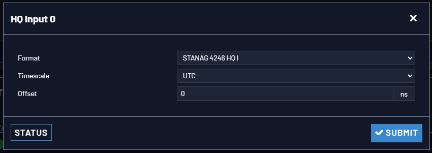
The Edit window allows the configuration of the following settings:
- Format: Used to configure the formatting of the four available HAVE QUICK outputs. The available output formats are as follows:
- STANAG 4246 HQ I
- STANAG 4246 HQ II
- STANAG 4430 STM
- STANAG 4430 Ext HQ
- ICD-GPS-060A BCD
- ICD-GPS-060A HQ
- DOD-STD-1399 BCD
- Timescale: Used to select the time base for the incoming time code data. The entered Timescale is used by the system to convert the time in the incoming data stream to UTC time for use by the System Time. The available choices are:
- UTC: Coordinated Universal Time ("temps universel coordonné"), also referred to as ZULU time
- TAI: Temps Atomique International
- GPS: The raw GPS time as transmitted by the GNSS satellites (as of <D-M-Y>, this is 18 seconds ahead of UTC time)
- Offset: Provides the ability to account for HAVE QUICK cable delays or other latencies in the HAVE QUICK outputs. The Offset values are entered in nanoseconds (ns). The available Offset range is –500 to +500 ms.
Configuring an IRIG Input
An IRIG Input is available by default configuration through the Multi-I/O connector (see Configurable Connectors).
Unless you have an IRIG option card, IRIG AM is not available as an input at this time.
To configure the IRIG Input (also referred to as ‘Reference’), navigate to its Edit window.
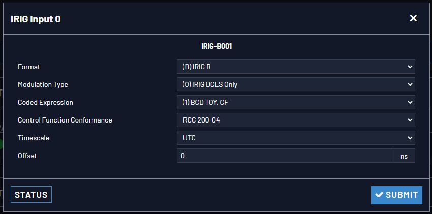
The Edit window allows the configuration of the following settings:
- Format: Sets the formatting of the IRIG input signal, as defined by the IRIG generator time source. The available choices are:
- IRIG A
- IRIG B
- IRIG G
- NASA-36
- Modulation Type: Configures the type of input signal modulation. The choices are:
- IRIG DCLS—A TTL (Phase) modulated signal.
- Frequency: The IRIG modulation frequency. This is determined by the configuration of Format and Modulation Type. See IRIG Carrier Frequencies for details.
- Coded Expression—Defines the data structure of the IRIG signal, where:
- BCD = Binary Coded Decimal
- TOY = Time of Year
- CF = Control Field
- SBS = Straight Binary Seconds
- The available options will vary according to the configurations of Format and Modulation Type.
- Control Function Field: IRIG signals have an optional section in the data stream that can be used to include additional information (such as the present year, for example). This field allows the Control Field section of the IRIG output to be defined. The available configurations are:
- Fields conform to RCC 200-04: IRIG spec 200-04 specified a location for year value, if included in this field.
- Fields conform to IEEC 37.118-2005 (IEEE 1344): Control Field contains year, leap second and daylight savings time information.
- Fields conform to Spectracom Format: Year is included in Control Field but not in the same location as RCC-2004 output (year is offset by one position).
- Fields conform to Spectracom FAA Format: A unique IRIG output Control Field that contains satellite lock status and time error flags.
- Fields conform to NASA Formats: Variants of IRIG B
- Fields confirm to Spectracom IEEE C37.118-2005: Has been extended to support one-month leap second notification
The available options will vary according to the configurations of Format and Modulation Type.
Note: If the Format value is changed, the Control Field and Coded Expression change to the default values for the given Format value. The user can only change the Control Field field and Coded Expression field to allowed values for the Format field.
It is recommended that the SecureSync administrator/operator only use this if they do not know what the IRIG Input Format is, and they wish to identify the signal type, or to determine if a signal is present.
- Local Clock: The incoming IRIG input time information may be provided as local time, but System Time may be configured as UTC time, so internal computations need to be performed. With the Timescale field set to “Local”, select the name of a previously created Local Clock. The Time Zone and DST rules, as configured in the Local Clock will be applied to the front panel time display.
- Offset: Provides the ability to account for IRIG cable delays or other latencies in the IRIG input. The Offset value is entered and displayed in nanoseconds (ns). The available Offset range is -500 to +500 ms.