Configuring Outputs
Depending on the type of output interface, some of its settings may be user-editable. To access these settings for a given output, choose one of the two methods described below.
For information on disabling and enabling outputs, see Signature Control
Note: The illustrations shown below are examples. The windows displayed in your Web UI may look differently.
How to Configure an Output
To access the user-editable settings of an Output, choose one of these two methods:
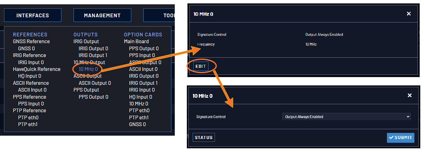
- Under INTERFACES > OUTPUTS, click the desired output.
- The Status window for the specific reference you selected will be displayed. Click the Edit button in the bottom-left corner.
- The settings window for the chosen output will be displayed. Edit the field(s) as desired.
- In the INTERFACES > OUTPUTS drop-down menu, click OUTPUTS, or one of the output categories (not indented to the right)
- In the Status window, click the GEAR button next to the desired output.
-
The settings window for the chosen output will be displayed. Edit the field(s) as desired.
The following configuration instructions apply to optional outputs on the basic unit model. For specifics on outputs made available through option cards, see the section Option Cards.
Note: Offset values for outputs are set in 20 ns increments and will round to the nearest multiple of 20 if not set to one exactly.
Configuring a 1PPS Output
A 1PPS Output is available by default configuration through the BNC connector, and can also be output through the Multi-I/O connector (see Configurable Connectors).
To configure a 1PPS output:
- Navigate to INTERFACES: OUTPUTS, or to INTERFACES: OPTION CARDS (white on orange).
- In the panel on the right, click the GEAR button next to the 1PPS Output you want to edit.
- The 1PPS Output Edit window will display, allowing the following items to be configured:
- Signature Control: Determines when the output is enabled. For more information, see Signature Control.
- Offset [ns]: Allows to offset the system's 1PPS on-time point, e.g. to compensate for cable delays and other latencies [range = –500000000 to 500000000 ns = ±0.5 s].
- Edge: Used to determine if the on-time point of the 1PPS output is the rising or the falling edge of the signal.
- Rising
- Falling
- Pulse Width [ns]: Configures the Pulse Width of the 1PPS output.
-
Click Submit.
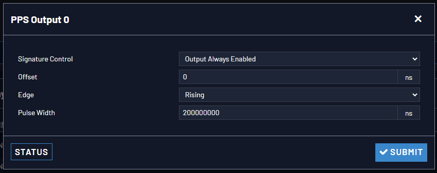
[range = 20 to 900000000 ns = 0.0 μs to 0.9 s]
[default = 200 ms]
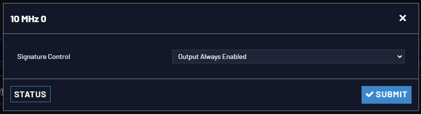
Configuring the 10 MHz Output
A 10 MHz Output is available on the rear panel of the SecureSync 2400 Time and Frequency Synchronization System.
To configure the 10 MHz output:
- Navigate to INTERFACES > OUTPUTS, or to INTERFACES > OPTION CARDS (white on orange).
- In the panel on the right, click the GEAR button next to the 10 MHz output that you want to edit.
- The 10 MHz edit window will display. Choose a value from the Signature Control field drop-down list to determine what SecureSync shall do with the output signal in the event its input reference is lost. For more information, see Signature Control.
- Click Submit.
Configure an ASCII Output
An ASCII Output is available by default and configuration through the Multi-I/O connector (see Configurable Connectors).
To configure the ASCII Output, go to its Edit window.
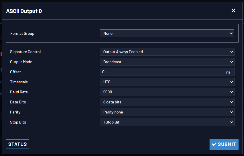
The Output Edit window allows the configuration of the following settings:
- Format Group – configures the message format type. Choices are:
- None (no message will be output)
- Spectracom
- NMEA
- BBC
- ICD-153
- EndRun
Once selected, the Format Group may offer a choice of Formats. For more information on supported Formats, see Time Code Data Formats.
- Format 1: Selects either the first of up to three, or the only format message to be output.
- Format 2: Selects the second consecutive format message to be outputted. Select “None” if only one output format is desired. “None” will be the only choice available if Format 1 is “None.”
- Format 3: Selects the third consecutive format message to be outputted. Select “None” if only one output format is desired. “None” will be the only choice available if Format 2 is “None.”
- Signature Control: Signature Control controls when the selected ASCII data output format will be present; see Signature Control.
- Output Mode: This field determines when the output data will be provided. The available Mode selections are as follows:
- Broadcast: The format messages are automatically sent out on authorized condition (Signature control), every second a message is generated in sync with the 1PPS.
- Request (On-time): A format message is generated in sync with 1PPS after the configured request character has been received.
- Request (Immediate): A format message is generated as soon as the request character is received. As this selection does not correlate the output data to the on-time point for the message, in Data Formats that do not provide sub-second information (such as Formats 0 and 1 whereas Format 2 provides sub-second information), it should be noted that the output data can be provided immediately, but a time error could occur when using the on-time point of the message in addition to the data for timing applications.
Note: The choices available in this field are determined by the choices of Format Group and Format.
- Time Scale: Used to select the time base for the incoming data. The entered Timescale is used by the system to convert the time in the incoming data stream to UTC time for use by the System Time. The available choices are:
- UTC: Coordinated Universal Time ("temps universel coordonné"), also referred to as ZULU time
- TAI: Temps Atomique International
- GPS: The raw GPS time as transmitted by the GNSS satellites (as of <D-M-Y>, this is currently 18 seconds ahead of UTC time).
If GPS or TAI time is used, then the proper timescale offsets must be set on the MANAGEMENT/OTHER/Time Management page. (See The Time Management Screen for more information on how to configure and read the System Time). Local timescale allows a Local Clock to apply a time offset for Time Zone and DST correction.
- A Local Clock can be set up through the Time Management page: This option will appear under the name of the local clock you have set up. See for more information. Local timescale allows a Local Clock to apply a time offset for Time Zone and DST correction.
The incoming input time information may be provided as local time, but System Time may be configured as UTC time, so internal computations need to be performed. With the Timescale field set to “Local”, select the name of a previously created Local Clock. The Time Zone and DST rules, as configured in the Local Clock will be applied to the front panel time display. See for more information on Local Clocks.
- Baud Rate: Determines the speed at which the output port will operate.
- Data Bits: Defines the number of Data Bits for the output port.
- Parity: Configures the parity checking of the output port.
- Stop Bits: Defines the number of Stop Bits for the output.
To view the current settings of the ASCII Input (also referred to as ‘Reference’), go to its Status window. For instructions, see: Viewing Input/Output Configuration Settings.
Configuring a GPIO Output
A GPIO Output is available through the BNC and/or Multi-I/O connector on the rear panel (see Configurable Connectors).
Note: The fields viewable will depend on the selection for the Output Mode.
- Output Mode:
- Direct Output Value: Output will be low or high, determined by the Output Value section below.
- Square Wave: Output will generate a programmable square wave determined by the configuration.
- Output Enabled: Check this box to enable or disable the output. If Enabled, additional configurable parameters will be displayed.
- Output Value: Determines the output level (Low or High).
- Signature Control: Controls when the output will be present. See also: Signature Control.
- Edge: Used to determine if the on-time point of the output is the Rising or Falling edge of the signal.
- Offset: Accounts for cable delays and other latencies [nanoseconds].
- Period: Sets the period of the square wave (in ns or µs scale).
- The wave’s frequency will display at the top of the window once you have configured the output. The frequency is calculated based on the Period and Period Correction settings.
- Period Correction: Period correction allows for the generation of more precise frequencies at the expense of additional period jitter. Over a length of time, the true square wave period comes to:
- Period + [(numerator/denominator) * 5 ns]
- Pulse Width: Pulse width of the output [nanoseconds].
- On-Time Point Pulse Width: The on-time point pulse width is the pulse width of the first square wave pulse aligned to the 1PPS On-Time Point. This is only active when the alignment count is non-zero [nanoseconds].
- Alignment Count(s): The alignment counter determines how often (in seconds) the square wave will be aligned back to the 1PPS. Setting zero will disable PPS alignment beyond the initial alignment.
- Time Alignment: (Enabled/Disabled) The time alignment enable changes the function of the alignment counter to align the square wave whenever the current time’s seconds value is a multiple of the alignment count. For example: If time alignment is enabled and alignment count is set to 15 seconds, the square wave will be aligned to the 1PPS when the seconds value on the time display equals 00, 15, 30, 45.
- Re-Initialize: Re-initializes square wave generation and aligns to 1PPS.
Configuring a HaveQuick Output
A HaveQuick Output is available by default configuration through the Multi-I/O connector and can be optionally configured through the BNC connector on the rear panel (see Configurable Connectors).
To configure the settings of a HAVE QUICK Output, go to its Edit window.
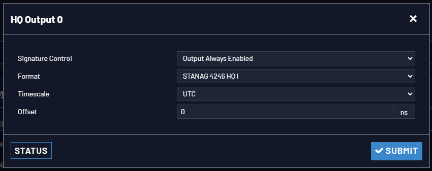
The Edit window allows the configuration of the following settings:
- Signature Control: Signature Control is used to control when the HAVE QUICK modulation is present, see Signature Control.
- Format: Used to configure the formatting of the four available HAVE QUICK outputs. The available output formats are as follows:
- STANAG 4246 HQ I
- STANAG 4246 HQ II
- STANAG 4372 HQ IIA
- STANAG 4430 Ext HQ (Extended HAVE QUICK)
- STANAG 4430 STM (Standard Time Message)
- ICD-GPS-060A BCD
- ICD-GPS-060A HQ
- DOD-STD-1399 BCD
- Timescale: Used to select the time base for the incoming time code data. The entered Timescale is used by the system to convert the time in the incoming data stream to UTC time for use by the System Time. The available choices are:
- UTC: Coordinated Universal Time ("temps universel coordonné"), also referred to as ZULU time
- TAI: Temps Atomique International
- GPS: The raw GPS time as transmitted by the GNSS satellites (as of <D-M-Y>, this is 18 seconds ahead of UTC time).
- A local clock set up through the Time Management Page: This option will appear under the name of the local clock you have set up. Refer to The Time Management Screen for more information on how to configure and read the System Time. Local timescale allows a Local Clock to apply a time offset for Time Zone and DST correction.
The incoming input time information may be provided as local time, but System Time may be configured as UTC time, so internal computations need to be performed. With the Timescale field set to “Local”, select the name of a previously created Local Clock. The Time Zone and DST rules, as configured in the Local Clock will be applied to the front panel time display. Refer to for more information on Local Clocks.
- Offset: Provides the ability to account for HAVE QUICK cable delays or other latencies in the HAVE QUICK outputs. The Offset values are entered in nanoseconds (ns). The available Offset range is –500 to +500 ms.
Configuring an IRIG Output
IRIG DCLS Output is available through the Multi I/O connector in the default settings (pins 6 & 7), and can also be configured on the DCLS OUT BNC connector on the rear panel, as well as through the multi I/O connector on either of the two RS485 channels (pins 3, 13, and 8, and pins 4, 14, and 9). See Configurable Connectors for more information. None of these listed channels allow IRIG AM outputs.
IRIG AM Output is available in the default configuration through the IRIG AM Output channel (pins 11 & 12) o(n the Multi I/O connector Additional outputs of IRIG AM would require an option card..
In the default configuration:
- IRIG Output 0 represents IRIG DCLS output (pins 6 & 7). This channel can only be DCLS.
- IRIG Output 1 represents the IRIG AM output (pins 11 & 12). This setting can only be configured to AM.
The numbering of outputs and inputs can change during pin layout changes (and when option cards are added).
Possible settings will be limited by the interface you are configuring.
To configure the settings of one of the two IRIG Outputs, go to its Edit window. For instructions, see: Configuring Option Card Inputs/Outputs.
Note: The choices available will change based on the type of IRIG you have chosen to configure.
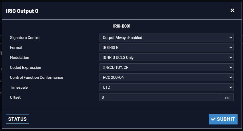
The Edit window allows the configuration of the following settings:
- Signature Control: Is used to control when the IRIG modulation will be present. This function allows the modulation to stop under certain conditions; see also Signature Control.
- Format: Used to configure the desired IRIG output formatting. The available choices are:
- IRIG A
- IRIG B
- IRIG G
- IRIG E
- NASA-36
- Modulation: Changes the type of output signal modulation. The available choices are:
- IRIG DCLS—A TTL-modulated output.
- IRIG AM-–An amplitude modulated output. The amplitude of the output is determined by the value entered in the Amplitude field.
- Frequency—The IRIG modulation frequency. This is determined by the configuration of Format and Modulation Type. See also IRIG Carrier Frequencies.
- Coded Expression: Defines the data structure of the IRIG signal, where:
- BCD = Binary Coded Decimal
- TOY = Time of Year
- CF = Control Field
- SBS = Straight Binary Seconds
- The available options will vary according to the values of Format and Modulation Type.
- Control Function Field: IRIG signals have an optional section in the data stream that can be used to include additional information (such as the present year, for example). This field allows the Control Field section of the IRIG output to be defined. The available configurations are:
- Fields conform to RCC 200-04: IRIG spec 200-04 specified a location for year value, if included in this field.
- Fields conform to IEEC 37.118-2005 (IEEE 1344): Control Field contains year, leap second and daylight savings time information.
- Fields conform to Spectracom Format: Year is included in Control Field but not in the same location as RCC-2004 output (year is offset by one position).
- Fields conform to Spectracom FAA Format: A unique IRIG output Control Field that contains satellite lock status and time error flags.
- Fields conform to NASA Formats: Variants of IRIG B
- Fields confirm to Spectracom IEEE C37.118-2005: Has been extended to support one-month leap second notification
The available options will vary according to the configurations of Format and Modulation Type.
- Timescale: Used to select the time base for the incoming time code data. The entered Timescale is used by the system to convert the time in the incoming data stream to UTC time for use by the System Time. The available choices are:
- UTC—Coordinated Universal Time ("temps universel coordonné"), also referred to as ZULU time
- TAI—Temps Atomique International
- GPS—The raw GPS time as transmitted by the GNSS satellites (as of <D-M-Y>, this is 18 seconds ahead of UTC time).
- A local clock set up through the Time Management Page—This option will appear under the name of the local clock you have set up. See Local Clock(s), DST for more information. Local timescale allows a Local Clock to apply a time offset for Time Zone and DST correction.
- Amplitude: The peak-to-peak output voltage level into a 600 Ω load is adjusted by entering a digital control value in this field. The level adjustment has no effect on TTL outputs, only on AM formats. The value of 128 will cause the Mark amplitude to be about 5Vp-p into high impedance. A value of 200 results in an output amplitude of about 9Vp-p into high impedance.
Note: These are nominal values only. Actual values will vary from unit to unit. To adjust the level precisely, connect an oscilloscope to the output connector when adjusting.
- Offset: Provides the ability to account for IRIG cable delays or other latencies in the IRIG input. The Offset value is entered and displayed in nanoseconds (ns). The available Offset range is -500 to +500 ms.
For IRIG frequency and output specifications, see IRIG Standards and Specifications.