+1.585.321.5800
Antenna Settings
Several antenna-related settings can be configured to allow for optimal scenario simulation: antenna gain pattern, lever arm, and elevation mask.
To configure these settings, navigate to: Select [Select Scenario] > Configure Scenario: View 2/3: Antenna.
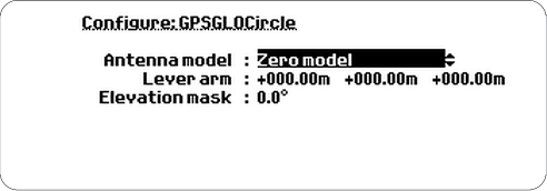
Antenna model
The antenna gain pattern can be specified for each scenario, using a set of pre-defined antenna models, or by utilizing a user-specified file. The built-in antenna models assume an omni-directional gain pattern where the maximum gain is to be found towards the zenith.
The pre-defined antenna models are:
- Zero model: Isotropic antenna with a gain of 0 dBic towards all directions. This is the default.
- Patch: Gain pattern approximates TOKO DAK Series patch antenna with maximum gain +5 dBic. Size of the patch is 25 x 25 mm and ground plane 70 x 70 mm.
- Helix: Gain pattern approximates Sarantel SL1200 (GeoHelix-P2) antenna pattern with maximum gain -2.8 dBic. This is a small helix antenna designed to be embedded in handheld devices e.g. mobile phones. See http://www.sarantel.com for details.
- Cardioid: Gain pattern 1+sin (elevation) with maximum gain +3 dBic.
- GPS-703-GGG: Gain pattern approximates Novatel’s GPS-703-GGG antenna with maximum gain of +5.7 dBic. See www.novatel.com for details.
The format used to describe gain patterns is the FEKO pattern file format version 6.1, Far Field format, File Format 2.0. Gain patterns for various frequencies are to be included in the same file as separate Solution Blocks. The GSG units expect the result type to be either Gain or Directivity, and enforces a maximum value of 50 for the No. of Theta/Phi Samples, with 36 as the recommended choice yielding a 5/10 degree resolution on elevation/azimuth.
The first line of the antenna file is expected to define the File Type. The GSG defines phi 0 degrees, i.e. the x-axis of phi, to point towards the north direction.
Lever arm
A lever arm can be specified to separate the antenna position from the body mass center of the vehicle: All trajectory movements in the simulation will act on the body mass center of the vehicle. By default the antenna is located in this the body mass center position, pointing upward. To specify that the receiver antenna is not located in the body mass center position, a lever arm can be configured.
The lever arm settings specify the relative position change in the form of (x, y, z) along the body axis of the vehicle frame, where the coordinate system XYZ is aligned with the body mass center frame. At the start of a scenario, the X-axis corresponds to the east/west axes of the ENU frame and the nose is pointing to the north.
The X-axis has a positive direction towards the right side of the sensor. The Y-axis has a positive direction towards the front of the sensor. The Z-axis has a positive direction towards the top of the sensor.
For more information on vehicle modeling, see Environment models.
Elevation mask
The elevation mask specifies how low GNSS satellites will be simulated. The elevation mask is set to zero by default.
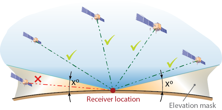
Elevation mask
A receiver typically has a higher elevation mask and it will not use any satellite below the elevation angle of its set mask. The recommended setting is to set the elevation mask of GSG to a value equal or less than that of the device under test.
In order to conserve channels by not generating signals the GNSS receiver will not use in its fix, the elevation mask in the GSG can be set to a slightly higher value. This is especially important with, e.g., GSG-52/53 Series units, or GSG-5 models equipped with 4-channels.