+1.585.321.5800
Interference signals
Note: The Interference feature is only available with GSG-5, GSG-55, GSG-56 and GSG-6 Series products. Some features are only available when OPT-JAM is enabled in the unit (see List of Available Options).
Orolia GSG-Series simulators can generate GNSS interference signals to test GNSS receiver performance. To configure an interference signal, navigate to Select > Select Scenario > Configure Scenario, View 2/3: Advanced: Interference Signals.
After specifying the desired number of interference signals (using the UP/DOWN arrow keys), press enter to display the first interference signal configuration view (the total number of views depends on how many interference signal you specified):
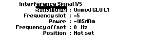
Interference configuration view
The following parameters can be configured:
Signal type
You can configure any signal type your GSG unit is licensed for (un-licensed signal types are grayed out).
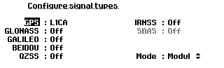
Interference signal type configuration view
The interference signal type can be:
- GPS: L1CA, L1P, L2P, L1P(Y), L2P(Y), GPS carrier, SBAS
- GLONASS: L1, L2 or GLONASS carrier
- Galileo: E1, E5a, E5b or a Galileo carrier
- BeiDou: B1,B2 or BeiDou B1,B2 carrier signal
- QZSS: L1CA or QZSS L1 carrier signal.
- If your GSG unit supports jamming simulations (OPT-JAM), sweep and narrowband noise are available as interference types.
Mode in the lower right-hand corner allows to further manipulate the interference signal by offering the following options:
- Modulated: standard signal type (default)
- PRN: Pseudo-Random Noise (see e.g., Navipedia: GNSS signal for more information)
- Unmodulated: carrier signal (carrier)
- Sweep (OPT-JAM only): A dialog is shown asking for startOffset, endOffset, and Sweep-Time.
- Noise (OPT-JAM only): A dialog is shown asking for startOffset, endOffset and SweepTime.
Offsets are used to specify the bandwidth and position of the sweep/noise related to the selected signal frequencies. The range of offsets is ±40 MHz, but can be less when the scenario is executed since signals are not centered in the middle of a frequency band.
Note: Noise interference is not available if wide band noise is set to ON under the Options > Transmit power menu.
For GPS, SBAS, Galileo, GLONASS, BeiDou, IRNSS and QZSS signals, the Satellite ID must be specified.
For GLONASS carrier signals the Frequency slot must be specified.
In some instances, this field is not applicable, and will be grayed out (e.g., GPS carrier).
The frequency offset refers to nominal frequency of the selected signal/frequency slot.
Power, Position
It is possible to simulate a location-based jamming signal by specifying a position for it. Location-based jamming simulation utilizes the jamming signal power, and position to calculate the distance from the simulated position, applying the path loss formula given earlier in this document (see Signal Power Level Considerations) to calculate the power of the received jamming signal. As the scenario position moves closer to the location of the jamming transmitter, the jamming power increases, and vice versa.
When configuring a location-based jamming source, the distance to the scenario start position and the jamming coverage are shown, in order to assist you in designing a reasonable jamming test configuration.
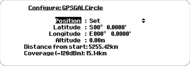
Configuring the position of a jamming source
Note that the jamming power can be set to +60 dBm, whereas the maximum GSG power level is -65 dBm.
Example
The figure below shows a configuration of a sweeper interference signal for the L1, L2 and L5 bands (OPT-JAM installed).
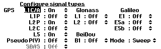
Configured sweeper signal