+1.585.321.5800
Rear Panel
As a means for communication, GSG supports GPIB, USB and Ethernet. Only one connection can be active at a time. The active connection is selected under Options > Interface. The default setting is Ethernet.
The illustration below shows the connections available on the back side of the unit:
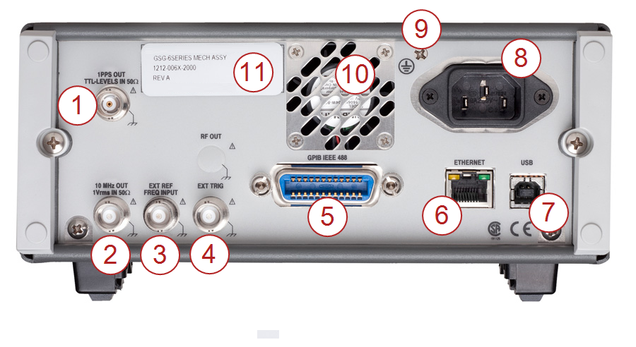
GSG rear panel
- 1PPS Output: TTL level signal with positive slope timed to GPS time of RF out (can be programmed as 10/100/1000PPS).
- Reference Output: 10 MHz derived from the internal or—if present—external reference.
- External Reference Input: Can be selected as a reference via the Interface and Reference menu.
- External Trigger Input: Optional signal input for scenario triggering.
- GPIB Connector: The address is set in the Interface and Reference menu.
- Ethernet Connector: Data communications port used with TCP/IP networks.
- USB Connector: Data communications port used with Personal Computers.
- Line Power Inlet: AC 90-265 VRMS. 45-440 Hz; automatic input voltage selection.
- Protective Ground Terminal: The protective ground wire is connected at this location inside the instrument. Never tamper with this screw!
- Fan: The fan speed is controlled via a temperature sensor. Normal bench-top use means low speed, whereas rack-mounting and/or installed options may result in higher speed.
- Type Plate: Indicates model number and serial number.