+1.585.321.5800
Mechanical Installation
For electrical installation, see Electrical Installation.
General Installation Considerations
GSG-Series units can be operated in any position, i.e. horizontal, vertical, or at any angle.
The air flow through the side ventilation openings must not be obstructed.
Leave 5 cm (2") of space around the unit.
For bench-top use, a fold-down support is available for use underneath the GNSS Simulator. This support can also be used as a handle to carry the instrument.
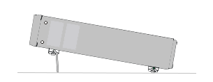
Fold-down support
With the optional Orolia 22/90 rack-mount kit (P/N 9446-1002-2901) one GSG unit can be installed in a 19-inch rack (2U). The kit comprises:
- 2 ears, one of which with a pre-assembled face-plate spacer
- 4 screws, M5 x 8
- 4 screws, M6 x 8.
Rack-Mount-Kit (the GSG housing shown in the center is not part of the kit)
In order to prepare the GSG unit for rack-mount installation, the housing needs to be opened, in order to remove the bottom feet (otherwise the assembly will not fit in a 2U slot.)
DANGER! Do not perform any work on the internal components of the unit, while the housing is removed, unless you are qualified to do so. Before removing the cover, unplug the power cord and wait for one minute to allow any capacitors to discharge.
- After making sure that the power cord has been unplugged, carefully turn the unit upside down.
- Temporarily remove the two rear feet by loosening their screws.
- Remove the four housing screws and plugs (if present) at the side panels; discard them.
- Grip the front panel with one hand, while pushing at the rear with the other hand. Pull the unit out of its housing.
- Remove the four bottom feet from the housing, as shown in the illustration below:
Use a screwdriver or a pair of pliers to remove the springs holding each foot, then push out the foot.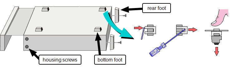
- Gently push the unit into its housing again.
- Re-assemble the two rear feet.
- Install the ears that came with the rack-mount kit. Use the rack-mount kit M5 housing screws.
- Depending on accessibility in your rack, you can connect the cables to the GSG unit now, or after installation of the assembly in the rack. For electrical installation, see Electrical Installation.
- Install the assembly in your rack, using the M6 screws that came with the rack-mount kit.
- Complete the electrical installation.
Preparing the GSG unit for rack mounting
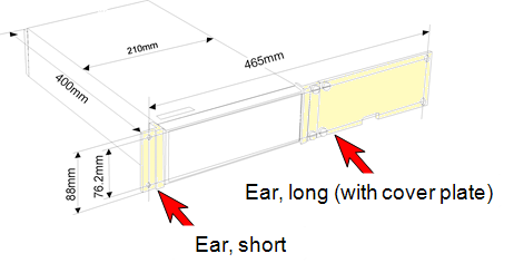
Part identification: ears
Note: The unit can also be installed on the right-hand side of the rack by reversing the two ears.
With the optional Orolia 22/05 rack-mount kit (P/N 1211-0000-0701), two GSG units can be installed side-by-side in one 19-inch rack (2U). The kit comprises:
- 4 x Bracket, rear (1211-1000-0706) [Item 1]
- 2 x Ear, rack (1211-1000-0714) [Item 2]
- 1 x Hinge, right half (1211-1000-0709) [Item 3]
- 1 x Hinge, left half (1211-1000-0709) [Item 4]
- 8 x Screw, oval head phil, M5x10mm (HM25R-D5R8-0010) [Item 5]
- 2 x Screw, pan head phil, M4x8mm (HM10R-04R0-0008) [Item 6]
- 1 x Spacer, Hex, M4x16 (HM50R-04R0-0016) [Item 7]
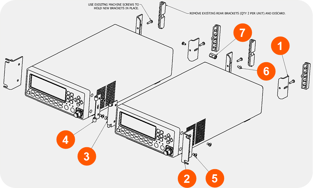
Dual rack-mount assembly
In order to prepare the GSG units for rack mount installation, the housings needs to be opened, in order to remove the bottom feet (otherwise the assembly will not fit in a 2U slot.)
DANGER! Do not perform any work on the internal components of a GSG unit, while the housing is removed, unless you are qualified to do so. Before removing the cover, unplug the power cord and wait for one minute to allow any capacitors to discharge.
- After making sure that the power cord has been unplugged, carefully turn the first GSG unit upside down.
- Remove the two rear feet. Keep the screws, discard the brackets.
- Remove the four housing screws and plugs (if present) at the side panels, and discard them.
- Grip the front panel with one hand, while pushing at the rear with the other hand. Pull the unit out of its housing.
- Remove the four bottom feet from the housing, as shown in the illustration below:
Use a screwdriver or a pair of pliers to remove the springs holding each foot, then push out the foot. - Gently push the unit into its housing again.
- Install the rear brackets supplied with the mounting kit (item no. 1) where the rear feet were previously attached (see illustration "Dual rack-mount assembly" above). Use the screws saved in step 2.
- Repeat the procedure described above for the second unit.
- Using a Philips-head screwdriver, screw the rack ears (item no. 2) into place, using the supplied 10-mm screws (item no. 5).
- Pinch the hinge pins together, to separate the right and left hinge halves (items no. 3 and 4).
- Attach hinge halves to the unit with the hinge facing towards the front.
- Pinch the hinge pins together into the stored position. Align the hinge halves together between the two units, and swing together side by side. The hinge pins should snap into place, securing the front of the two units.
- In the back of the unit, take the supplied Hex Spacer (item no. 7), and place between middle rear brackets, and secure using the supplied 8-mm screws (item no. 6).
- Assembly is now ready for installation into standard 19" rack.
- Depending on accessibility, you can complete the electrical installation before or after installing the assembly in the rack. For electrical installation, see Electrical Installation.
Preparing a GSG unit for rack mounting
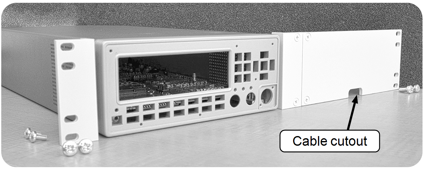
GSG units are frequently installed adjacent to an Agilent Power Meter, using one 19" slot (2U). This can be accomplished with the optional Orolia 22/04 rack-mount kit (P/N 9446-1002-2041). Also required is the Agilent rack-mount kit.
Note: This kit can also be used to install only one GSG unit in a 19" rack 2U slot, similar to the optional Orolia 22/90 Rack-Mount Kit (P/N 9446-1002-2901).
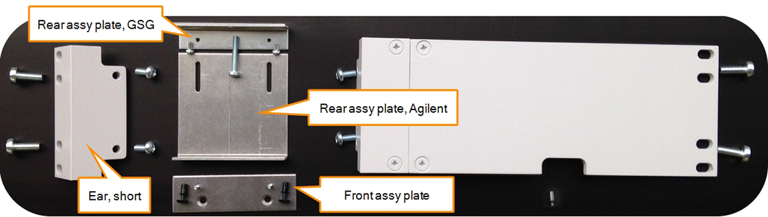
22/04 Rack-mount kit
In order to prepare the GSG unit for rack mount installation, the housing needs to be opened, in order to remove the bottom feet (otherwise the assembly will not fit in a 2U slot.) The same may be necessary for the Agilent unit – follow the manufacturer's instructions.
- After making sure that the power cord has been unplugged, carefully turn the GSG unit upside down.
- Temporarily remove the two rear feet by loosening their screws.
- Remove the four housing screws and plugs (if present) at the side panels, and discard them.
- Grip the front panel with one hand, while pushing at the rear with the other hand. Pull the unit out of its housing.
- Remove the four bottom feet from the housing, as shown in the illustration below:
Use a screwdriver or a pair of pliers to remove the springs holding each foot, then push out the foot. - Gently push the unit into its housing again.
- Re-assemble the two rear feet.
- Decide on which side of the assembly the GSG unit is to be installed: If on the left-hand side, install the short ear to the left hand side of the GSG unit, using the rack-mount kit M5 housing screws.
Preparing the GSG unit for rack mounting
Note: The instructions below are based on the assumption that the GSG unit is installed on the left-hand side of the assembly.
- Install the front assy plate to the Agilent unit, as shown in the illustration below. Use the screws from the Agilent rack-mount kit.
Take two of the plastic snap caps from the GSG rack-mount kit, remove and discard the caps, and install the sleeves into the housing screw openings.
Slide the Agilent unit and the GSG unit together, so that the protruding pins of the front assy plate fit into the sleeves.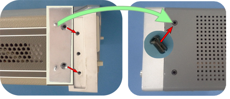
- Install the rear assy plate, Agilent, and the rear assy plate, GSG, and assemble them, as shown in the illustrations below.
- Equivalent to Step 8., install the front panel ear plate (Agilent rack-mount kit) to the Agilent power meter.
- The assembly is now complete, and can be installed in the cabinet.
Front assembly plate installation Agilent unit (shown left), GSG unit
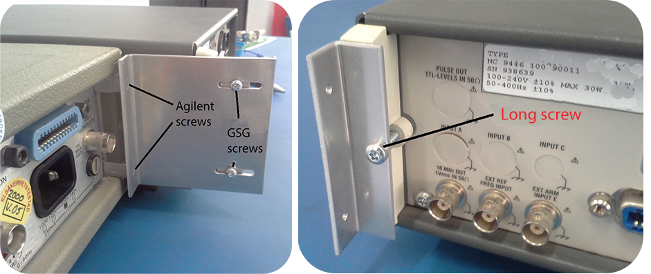
Installation of rear assembly plates