+1.585.321.5800
NetClock 9489 In-/Outputs
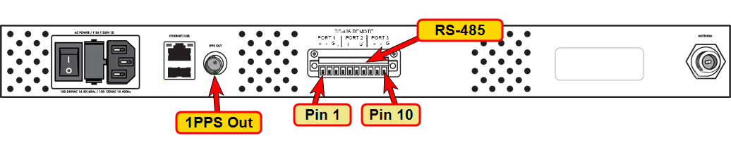
Rear panel NetClock Model 9489
1PPS Output
The NetClock 9489 1PPS Output is identical to the NetClock 9483. See 1PPS Output.
ASCII Time Code RS-485 Outputs and Input
NetClock 9489 provides two (2) ASCII RS-485 outputs, and one (1) ASCII RS-485 input.
Note: Units manufactured before April 2017 only have the two ASCII RS-485 Outputs, i.e. Pins 1-6.
ASCII outputs
The ASCII outputs provide NetClock with the ability to output one or two back-to-back ASCII time code data streams that can be provided to peripheral devices which accept an ASCII RS-485 input data stream for either their external time synchronization or for data processing.
ASCII input
The ASCII input provides a serial data interface between an ASCII time generator (e.g., another NetClock unit), serving as an input reference in order to synchronize NetClock (in conjunction with, or in lieu of, other available inputs, such as GNSS).
Accuracy
Accuracy: ±100…1000 µs (format dependent)
Configuring the RS-485 ASCII Input/Outputs
To configure the ASCII Input (also referred to as ‘Reference’) or ASCII Output, navigate to the corresponding Edit window under the INTERFACES menu in the Web UI (the Web UI list entries are under ASCII TIMECODE RS-485.)
Input Edit window:
- Format Group: Determines the time code message format category. Choices are:
- Auto
- Spectracom
- NMEA
- ICD-153
- EndRun
- Format: Once a Format Group has been selected, one or more Format fields may appear, allowing you to select one or more time code Formats.
Note: If Auto is chosen as the format group, the format will automatically be Auto-detect. NetClock will attempt to identify the format of the incoming ASCII message.
- Offset: Provides the ability to account for ASCII input cable delays or other latencies in the ASCII input. The Offset value is entered and displayed in nanoseconds (ns). The available Offset range is –500 to +500 ms.
- Timescale: Used to select the time base for the incoming ASCII time code data. The entered Timescale is used by the system to convert the time in the incoming ASCII data stream to UTC time for use by the System Time. The available choices are:
- UTC: Coordinated Universal Time ("temps universel coordonné"), also referred to as ZULU time
- TAI: Temps Atomique International
- GPS: The raw GPS time as transmitted by the GNSS satellites (as of July, 2015, this is 17 seconds ahead of UTC time)
- A local clock set up through the Time Management Page: This option will appear under the name of the local clock you have set up. Local timescale allows a Local Clock to apply a time offset for Time Zone and DST correction.
The incoming input time information may be provided as local time, but System Time may be configured as UTC time, so internal computations need to be performed. With the Timescale field set to “Local”, select the name of a previously created Local Clock. The Time Zone and DST rules, as configured in the Local Clock will be applied to the front panel time display. See for more information on Local Clocks.
Note: The Timescale of the ASCII input (as configured in the ASCII time source) must be set correctly, especially if other input references are enabled. Failure to configure the Timescale of the ASCII input correctly could result in time jumps occurring in the System Time when input reference changes occur. These time jumps could affect NTP and normal operation of the system.
- PPS Source – choices are:
- Message: The 1PPS on time point is extracted from the ASCII message received.
- Baud Rate: Determines the speed at which the input port will operate.
- Data Bits: Defines the number of Data Bits for the input output.
- Parity: Configures the parity checking of the input port.
- Stop Bits: Defines the number of Stop Bits for the input port.
Output Edit window:
- Format Group – configures the message format type. Choices are:
- None (no message will be output)
- Spectracom
- NMEA
- BBC
- ICD-153
- EndRun
Once selected, the Format Group may offer a choice of Formats.
- Format 1: Selects either the first of up to three, or the only format message to be output.
- Format 2: Selects the second consecutive format message to be outputted. Select “None” if only one output format is desired. “None” will be the only choice available if Format 1 is “None.”
- Format 3: Selects the third consecutive format message to be outputted. Select “None” if only one output format is desired. “None” will be the only choice available if Format 2 is “None.”
- Signature Control: Signature Control controls when the selected ASCII data output format will be present.
- Output Mode: This field determines when the output data will be provided. The available Mode selections are as follows:
- Broadcast: The format messages are automatically sent out on authorized condition (Signature control), every second a message is generated in sync with the 1PPS.
- Time Scale: Used to select the time base for the incoming data. The entered Timescale is used by the system to convert the time in the incoming data stream to UTC time for use by the System Time. The available choices are:
- UTC: Coordinated Universal Time ("temps universel coordonné"), also referred to as ZULU time
- TAI: Temps Atomique International
- GPS: The raw GPS time as transmitted by the GNSS satellites (as of July, 2015, this is currently 17 seconds ahead of UTC time).
If GPS or TAI time is used, then the proper timescale offsets must be set on the MANAGEMENT > OTHER > Time Management page.
- A Local Clock can be set up through the Time Management page: This option will appear under the name of the local clock you have set up. See for more information. Local timescale allows a Local Clock to apply a time offset for Time Zone and DST correction.
The incoming input time information may be provided as local time, but System Time may be configured as UTC time, so internal computations need to be performed. With the Timescale field set to “Local”, select the name of a previously created Local Clock. The Time Zone and DST rules, as configured in the Local Clock will be applied to the front panel time display. See for more information on Local Clocks.
- Baud Rate: Determines the speed at which the output port will operate.
- Data Bits: Defines the number of Data Bits for the output port.
- Parity: Configures the parity checking of the output port.
- Stop Bits: Defines the number of Stop Bits for the output.
Pin Layout
ASCII RS-485 pin assignment
| Pin | Signal | Function |
|---|---|---|
| 1 | RS-485 TX+ | ASCII Output 1 |
| 2 | RS-485 TX- | |
| 3 | GND | |
| 4 | RS-485 TX+ | ASCII Output 2 |
| 5 | RS-485 TX- | |
| 6 | GND | |
| 7 | RS-485 RX+ | ASCII Input |
| 8 | RS-485 RX- | |
| 9 | GND | |
| 10 | n/a | Not used |