+1.585.321.5800
Configuring an External Display Clock
A frequently requested configuration is to connect and configure a remote Spectracom TimeView® Display Clock to a NetClock unit.
.gif)
Spectracom TV400 series display clock
The following procedure applies to Spectracom display clocks, models TV400W, and TV210W.
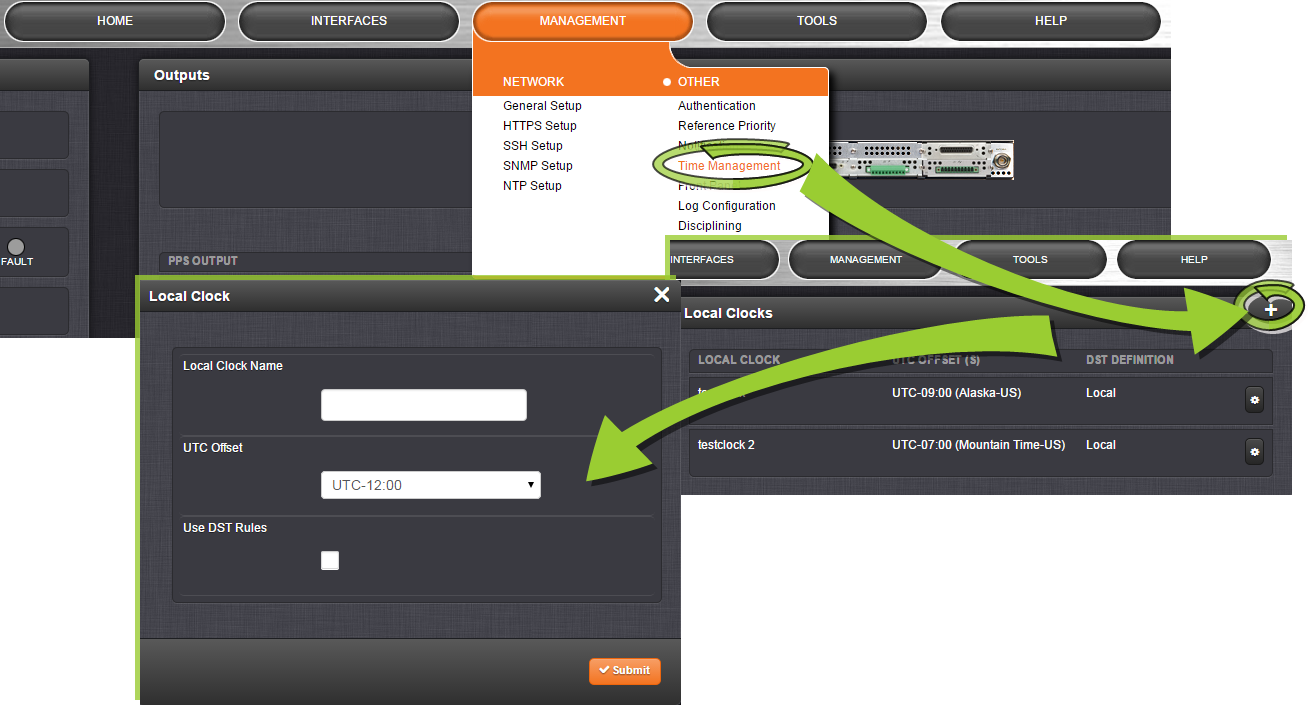
- Set up a Local Clock: In the Web UI, navigate to Management > Time Management, and click the PLUS icon to add a new Local Clock.
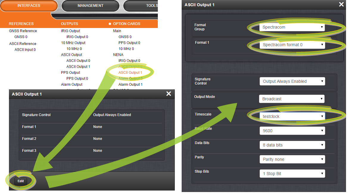
Name the new Local Clock, and configure it (for more information, see ). - Navigate to the INTERFACES menu, and select ASCII Output 1 (the RS-485 Output). In the window that opens, click the EDIT button:
- In ASCII Output 1 configuration window, select:
- Under Format Group: Spectracom
- Under Format 1: Spectracom Format 0, and
- Under Timescale: the Local Clock that you created in Step 1.
For additional information on the other settings, see Configuring an ASCII Time Code Output (RS-232 or RS-485).
- Click Submit. The RS-485 output has not been setup to supply the correct time and format for the display clock.
- Connect the NetClock RS-485 output to the display clock input.
Do not forget to install the 120 Ω terminating resistor (included with the display clock ancillary kit) between Pin 1 and Pin 2 of the terminal block of the display clock. - TESTING: Once the TV400W synchronizes, the seconds will stop flashing and the time will read the Local Time configured in your NetClock. If this does not happen, check the configuration, wiring and sync status of the NetClock 9483. The TV400W will not synchronize unless the GNSS is connected to your NetClock, and the unit is in sync.

Wiring the RS-485 signal
Note: The TV400W series display clock can be daisy chained from Input to Input, up to a total of 32 devices in a single chain. The terminating resistor should be installed in only the last clock in the daisy chain.