+1.585.321.5800
NENA-Compliant Module
NetClock 9483 is equipped with a NENA-compliant module which provides:
- IRIG support (including support for all NENA formats)
- ASCII RS-232 time code support
- ASCII RS-485 time code
- relay/alarms.
Note: This module is not available for NetClock 9489.
NENA-Compliant Module: Specifications
| Outputs: | (1) IRIG B/E, IEEE 1344/C37.118-2005 (AM/TTL) | (1) ASCII RS-232 | (1) ASCII RS-485 | (2) Relay/Alarm |
| Connectors: | BNC (J1) | DB9F (J2) | 3.81 mm Terminal block (J3) | |
| Accuracy: | ±20 to ±200 μs of UTC, format-dependent | ±100-1000 μs (format-dependent) | ±100-1000 μs (format-dependent) | Switch time 4ms, max. |
NENA module specifications
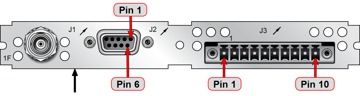
Rear plate of
IRIG Output Specifications
AM IRIG Output:
- Output impedance: 50 Ω nominal
- Amplitude (adjustable):
- 500 mVp-p min, 6Vp-p max into 50 Ω
- 1Vp-p min, 12 Vp-p max into > 600 Ω
- AM Carrier:
- IRIG A – 10 kHz
- IRIG B – 1kHz
- IRIG E – 100 Hz, 1kHz
- IRIG G – 100 kHz
- Modulation Ratio: 3.3:1 nominal
DCLS IRIG Output:
- Signal Level: 0V to 4.3 V (TTL compatible) into 50 Ω
- Output impedance of buffer is ~7 to 10 Ω
ASCII RS-232 Specifications
| Outputs: | ±5VDC minimum, ±5.4 VDC typical |
| Signal Type and Connector: | RS-232 DB-9F |
- RS-232 Input:
- -25 VDC to +25 VDC
- +0.6VIL min, +1.2VIL TYP
- +1.5VIH TYP, +2.4VIH MAX
- Input impedance > 3kΩ
- RS-232 Output:
- ±5VDC minimum
- ±5.4 VDC typical
- Output impedance 300 Ω, minimum
- -13.2 VDC to +13.2 VDC
- 1PPS Output:
- Signal level: 0V to 4.3 V (TTL compatible) into 50 Ω
- Output impedance of buffer is ~7 to 10 Ω
- Rise/fall times of ~20 nsec.
- Signal level: 0V to 4.3 V (TTL compatible) into 50 Ω
Pin Assignments
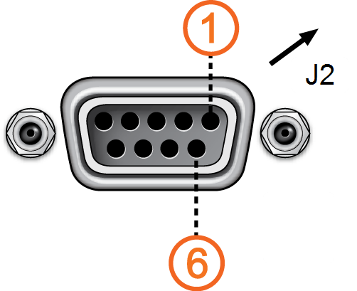
DB-9 connector "J2"
| Pin No. | Signal Name | Function |
|---|---|---|
|
Top row of 5 pins |
||
| 1 | PPS_OUT | 1PPS output |
| 2 | SERIAL_OUT_TX | RS-232 Transmit data |
| 3 | SERIAL_OUT_RX | RS-232 Receive data |
| 4 | NC | No connection |
| 5 | GND | Ground |
|
Bottom row of 4 pins |
||
| 6 | NC | No connection |
| 7 | NC | No connection |
| 8 | NC | No connection |
| 9 | NC | No connection |
ASCII RS-232 Output connector pin assignments
ASCII RS-485 and Alarms/Relays Specifications
| Inputs/Outputs: | (2) Two contact relay connections (NC, common, NO) |
| Signal Type and Connector: | Terminal block Contacts Switch under max. load of 30 VDC, 2A Contacts rated to switch 220 VDC Breakdown voltage of 1000 VDC between contacts Switch time 4ms, max. |
- RS-485 Differential Output:
- +1.65 V Typical Common Mode Output Voltage
- 2V min Differential Output Voltage Swing with 100 Ω load,
3.3 V Differential Output Voltage Swing, No Load, with ESD protection
Pin Assignments
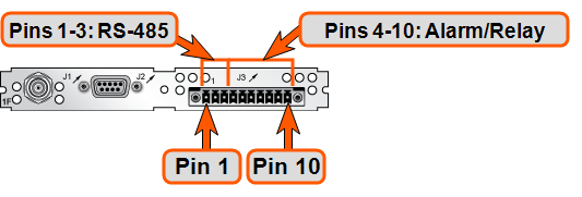
RS-485 connector "J3"
| Connector Pin | Signal | Direction | Characteristics |
|---|---|---|---|
| 1 | RS-485 TX+ | Out | 0V to 3VDC differential, 120 Ω load |
| 2 | RS-485 TX- | Out | 0V to 3VDC differential, 120 Ω load |
| 3 | GROUND | N/A | GROUND |
| 4 | Relay 1 NO | Out | Normally Open 30 VDC, 2A max. switching power |
| 5 | Relay 1 NC | Out | Normally Closed 30 VDC, 2A max. switching power |
| 6 | Relay 1 COMMON | Out | Common Contact 30 VDC, 2A max. switching power |
| 7 | Relay 2 NO | Out | Normally Open 30 VDC, 2A max. switching power |
| 8 | Relay 2 NC | Out | Normally Closed 30 VDC, 2A max. switching power |
| 9 | Relay 2 COMMON | Out | Common Contact 30 VDC, 2A max. switching power |
| 10 | GROUND | N/A | GROUND |
Relay/RS-485 outputs pin assignments
Note: The last device on each of the RS-485 remote output should be terminated into 120 Ω. Auxiliary Spectracom equipment (such as wall display clocks) include a 120 Ω resistor for termination.
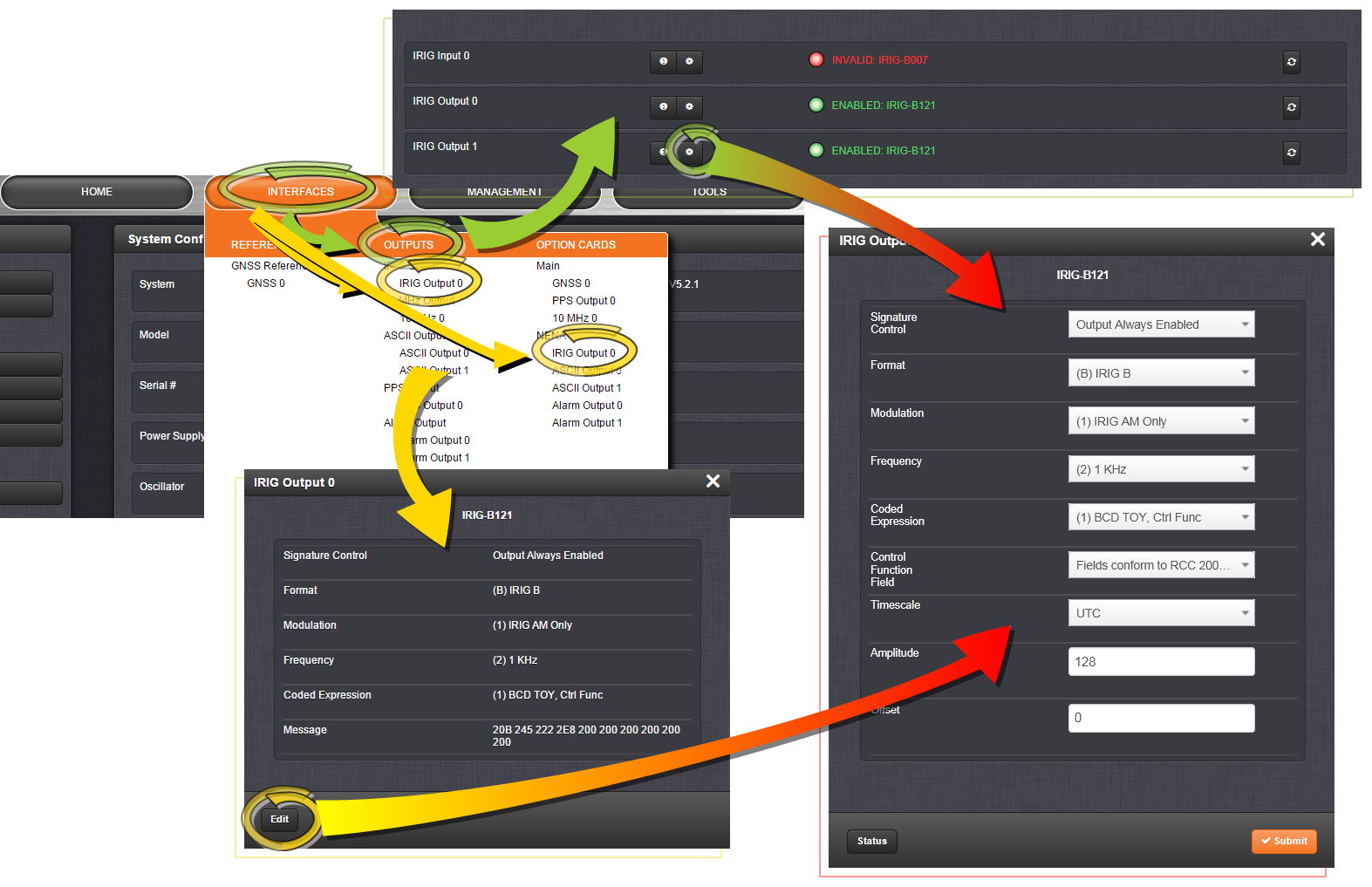
Configuring the IRIG Time Code Output
Via INTERFACES > OUTPUTS [or: INTERFACES > OPTION CARDS], navigate to IRIG Output 0. Depending on which path you take, you will need to click the GEAR button, or the Edit button in order to open the Edit window.
Note: If you have only one input or output of any type, NetClock will number that input or output 0. Additional inputs or outputs will be numbered 1 or above.
The IRIG output Edit window offers the following configuration fields:
- Signature Control: Used to control when the IRIG modulation will be present. This function allows the modulation to stop under certain conditions; see also Signature Control.
- Format: Defines the desired IRIG output formatting. Available options include: IRIG A, B, G, NASA-36, IRIG E (100 Hz or 1kHz)
- Modulation: Changes the type of output signal modulation:
- IRIG AM is an amplitude modulated output. The amplitude of the output is determined by the value entered in the “Amplitude” field.
- IRIG DCLS is a TTL modulated output.
- Frequency: If AM modulation is chosen above, the frequency is offered. Otherwise No Carrier is displayed.
- Coded Expression: Defines the data structure of the IRIG signal, where:
- BCD = Binary Coded Decimal
- TOY = Time of Year
- CF = Control Field
- SBS = Straight Binary Seconds
- Control Function Field: IRIG signals have an optional section in the data stream that can be used to include additional information (such as the present year, for example). This field allows the Control Field section of the IRIG output to be defined. The available configurations are as follows:
- RCC-2004: IRIG spec 200-04 specified a location for year value, if included in this field.
- IEE 1344 (C37.118-2005): IRIG B format with extensions. Control Field contains year, Leap Second and DST information.
- Spectracom Format: Year is included in Control Field but not in the same location as RCC-2004 output (year is offset by one position).
- Spectracom FAA Format: A unique IRIG output Control Field that contains satellite lock status and time error flags.
- NASA: A variant of IRIG B.
- Time Scale: Used to select the time base for the incoming time code data. The entered Timescale is used by the system to convert the time in the incoming data stream to UTC time for use by the System Time. The available choices are:
- UTC: Coordinated Universal Time ("temps universel coordonné"), also referred to as ZULU time
- TAI: Temps Atomique International
- GPS: The raw GPS time as transmitted by the GNSS satellites (as of July, 2015, this is 17 seconds ahead of UTC)
- A local clock set up through the Time Management Page: This option will appear under the name of the local clock you have set up (see Local Clock(s), DST). Local timescale allows a Local Clock to apply a time offset for Time Zone and DST correction.
- Amplitude: The peak-to-peak output voltage level into a 600 Ω load is adjusted by entering a digital control value in this field. The level adjustment has no effect on TTL outputs, only on AM formats. The value of 128 will cause the Mark amplitude to be about 5Vp-p into high impedance. A value of 200 results in an output amplitude of about 9Vp-p into high impedance.
Note: These are nominal values only. Actual values will vary from unit to unit. To adjust the level precisely, connect an oscilloscope to the output connector when adjusting.
-
Offset: Provides the ability to account for IRIG cable delays or other latencies in the IRIG input. The Offset value is entered and displayed in nanoseconds (ns). The available Offset range is -500 to +500 ms.
Each IRIG code specifies a carrier frequency that is modulated to encode date and time, as well as control bits to time-stamp events. Initially, IRIG applications were primarily military and government associated. Today, IRIG is commonly used to synchronize voice loggers, recall recorders, and sequential event loggers found in emergency dispatch centers and power utilities.
For more information on IRIG frequency and output specifications, see IRIG Standards and Specifications.
Configuring an ASCII Time Code Output (RS-232 or RS-485)
Note: The process of configuring the ASCII Time Code output is independent of the communications protocol.
Via INTERFACES > OUTPUTS [or: INTERFACES > OPTION CARDS], navigate to the ASCII Output you want to configure. Depending on which path you take, you will need to click the GEAR button, or Edit button in order to open the Edit window:
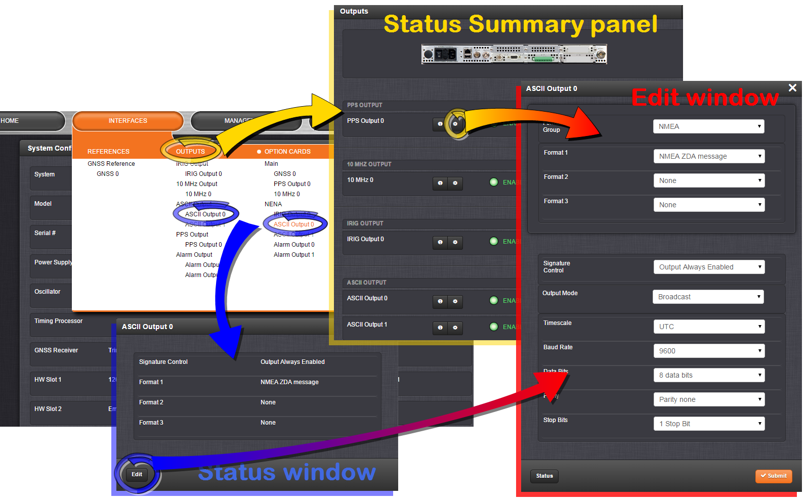
Note: If you have only one input or output of any type, NetClock will number that input or output 0. Additional inputs or outputs will be numbered 1 or above.
The Edit window offers the following configuration fields:
- Format Group: Determines the time code message format category (see also Time Code Data Formats). Choices are:
- None
- NENA-Spectracom (Formats 0, 1, 2, 3, 4, 7, 8, 9, 1S)
- NMEA (GGA, RMC, ZDA message)
- BBC (Formats 1, 2, 3 PSTN, 4, 5 RMC)
- ICD-153 (Buffer Box, Time Transfer, Current Status)
- EndRun (EndRun Time Format, Endrun X Format)
- Format: Once a Format Group has been selected, one or more Format fields may appear, allowing you to select one or more time code Formats. For more information on time code formats, see Time Code Data Formats.
-
The choice of format group determines t he format choices available in the Format 1, Format 2 and Format 3 fields.
- Format 1: Selects either the first of up to three, or the only format message to be output. See Time Code Data Formats for a description of available formats.
- Format 2: Selects the second consecutive format message to be outputted. Select “None” if only one output format is desired. See Time Code Data Formats for a description of available formats.
- Format 3: Selects the third consecutive format message to be outputted. Select “None” if only one output format is desired. See Time Code Data Formats for a description of available formats.
-
The choice of format group determines t he format choices available in the Format 1, Format 2 and Format 3 fields.
- Signature Control: Used to control when the IRIG modulation will be present. This function allows the modulation to stop under certain conditions; see also Signature Control.
- Output Mode: This field determines when the output data will be provided. The available Mode selections are as follows:
- Broadcast: The format messages are automatically sent out on authorized condition (Signature control), every second a message is generated in sync with the 1PPS.
- Request (On-time): A format message is generated in sync with 1PPS after the configured request character has been received.
- Request (Immediate): A format message is generated as soon as the request character is received. As this selection does not correlate the output data to the on-time point for the message, in Data Formats that do not provide sub-second information (such as Formats 0 and 1 whereas Format 2 provides sub-second information), it should be noted that the output data can be provided immediately, but a time error could occur when using the on-time point of the message in addition to the data for timing applications.
- Timescale: Used to select the time base for the incoming ASCII time code data. The entered Timescale is used by the system to convert the time in the incoming ASCII data stream to UTC time for use by the System Time. The available choices are:
- UTC: Coordinated Universal Time ("temps universel coordonné"), also referred to as ZULU time
- TAI: Temps Atomique International
- GPS: The raw GPS time as transmitted by the GNSS satellites (as of July, 2015, this is 17 seconds ahead of UTC time)
- A local clock set up through the Time Management Page: This option will appear under the name of the local clock you have set up. Refer to The Time Management Screen for more information on how to configure and read the System Time. Local timescale allows a Local Clock to apply a time offset for Time Zone and DST correction.
The incoming input time information may be provided as local time, but System Time may be configured as UTC time, so internal computations need to be performed. With the Timescale field set to “Local”, select the name of a previously created Local Clock. The Time Zone and DST rules, as configured in the Local Clock will be applied to the front panel time display. See .
Note: The Timescale of the ASCII input (as configured in the ASCII time source) must be set correctly, especially if other input references are enabled.
Failure to configure the Timescale of the ASCII input correctly could result in time jumps occurring in the System Time when input reference changes occur. These time jumps could affect NTP and normal operation of the system.
- Baud Rate: Determines the speed that the output port will operate at.
- Data Bits: Defines the number of data bits for the output port.
- Parity: Configures the parity checking of the output port.
- Stop Bits: Defines the number of stop bits for the output.
Configuring the Relay/Alarm Output
To manage the alarm relays:
- Via the INTERFACES > Alarm Output drop-down menu, navigate to the Alarm Output entry for the card you wish to configure. Depending on the path taken, …
- … click Edit or the GEAR button to edit the Alarm Output settings, or
- … click Status or the INFO button to view the current settings for the Alarm Output:
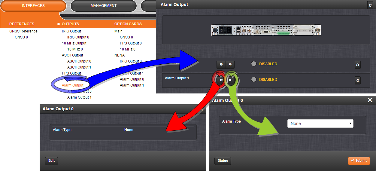
- The Alarm Type options displayed/to choose from are:
- None: Will not output for an alarm.
- Minor: Will output on a minor alarm.
- Major: Will output on a major alarm.