+1.585.321.5800
IRIG E Output
The IRIG E code contains the Binary Coded Decimal (BCD) time of year and Control Functions. The figure IRIG E Time Code Description illustrates the IRIG E data structure. The BCD time of year provides the day of year, 1-366, and time of day to tens of seconds. The hour of the day is expressed in 24 hour format. The Control Function field includes a time synchronization status bit, year information and SBS time of day.
- Time frame: 10 seconds.
- Code Digit Weighting:
- Binary Coded Decimal time of year.
- Code world - 26 binary digits.
- Tens of seconds, minutes, hours, and days.
- Recycles yearly.
- Code Word Structure: BCD word tens of seconds digits begin at index count 6. Binary coded elements occur between position identifier elements P0 and P5 (3 for seconds, 7 for minutes, 6 for hours, and 10 for days) until the code word is complete. An index marker occurs between decimal digits in each group to provide separation for visual resolution. Least significant digit occurs first.
- Control Functions: IRIG formats reserve a set of elements known as Control Functions (CF) for the encoding of various control, identification, or other special purpose functions. IRIG E has 45 Control Functions located between elements 50 and 98. The SecureSync uses the Control Function field to encode year data, time synchronization status, and SBS time data. Table B-2 lists the Control Function Field and each element's function.
Element 55 is the time synchronization status bit. Element 55 is a Binary 1 when the front panel time synchronization lamp is green, and a Binary 0 when the lamp is red.
Year information consists of the last two digits of the current year (i.e. 98, 99, etc.). Elements 60 through 63 contain the binary equivalent of year units. Elements 65 through 68 contain the binary equivalent of tens of years. In keeping with IRIG formats, the least significant bit occurs first.
Elements 80 through 97 are encoded with the Straight Binary Seconds (SBS) time data. The SBS time data is incremented in 10-second steps and recycles every 24 hours.
- Pulse rates:
- Element rate: 10 per second.
- Position identifier rate: 1 per second.
- Reference marker rate: 1 per 10 seconds.
- Element identification: The "on time" reference point for all elements is the pulse leading edge.
- Index marker (Binary 0 or uncoded element): 20 millisecond duration.
- Code digit (Binary 1): 50 millisecond duration.
- Position identifier: 80 millisecond duration.
- Reference marker: 80 millisecond duration, 1 per 10 seconds. The reference marker appears as two consecutive position identifiers. The second position identifier or reference marker is the on-time point for the succeeding code word.
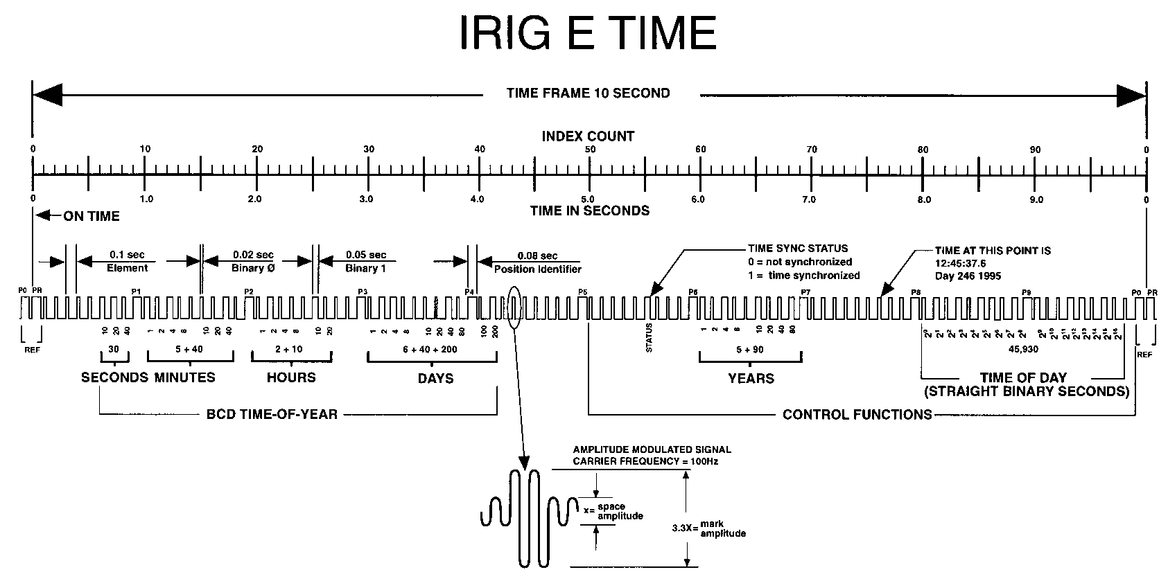
IRIG E time code description
The beginning of each 10 second time frame is identified by two consecutive 80 ms elements (P0 and PR). The leading edge of the second 80 ms element (PR) is the "on time" reference point for the succeeding time code. 1PPS position identifiers P0, P1 … P9 (80 ms duration) occur 0.1 s before 1PPS "on time" and refer to the leading edge of the succeeding element.
The time code word and the control functions presented during the time frame are pulse-width coded. The binary "zero" and index markers have a duration of 20 ms, and the binary "one" has a duration of 50 ms. The leading edge is the 10 pps "on time" reference point for all elements.
The binary coded decimal (BCD) time-of-year code word consists of 26 digits beginning at index count 6. The binary coded subword elements occur between position identifiers P0 and P5 (3 for seconds; 7 for minutes; 6 for hours; 10 for days) until the code word is complete. An index marker occurs between the decimal digits in each subword to provide separation for visual resolution. The least significant digit occurs first. The BCD code recycles yearly.
Forty-five control functions occur between position identifiers P5 and P0. Any control function element for combination of control function elements can be programmed to read a binary "one" during any specified number of time frames. Each control element is identified on the Control Function Field Table.
IRIG E control function field
| BIT No. | CF ELEMENT No. | FUNCTION |
|---|---|---|
| 50 | 1 | SPACE |
| 51 | 2 | SPACE |
| 52 | 3 | SPACE |
| 53 | 4 | SPACE |
| 54 | 5 | SPACE |
| 55 | 6 | TIME SYNC_STATUS |
| 56 | 7 | SPACE |
| 57 | 8 | SPACE |
| 58 | 9 | SPACE |
| 59 | PID P6 | POSITION IDENTIFIER |
| 60 | 10 | YEAR UNITS Y1 |
| 61 | 11 | YEAR UNITS Y2 |
| 62 | 12 | YEAR UNITS Y4 |
| 63 | 13 | YEAR UNITS Y8 |
| 64 | 14 | SPACE |
| 65 | 15 | YEAR TENS Y10 |
| 66 | 16 | YEAR TENS Y20 |
| 67 | 17 | YEAR TENS Y40 |
| 68 | 18 | YEAR TENS Y80 |
| 69 | PID P7 | POSITION IDENTIFIER |
| 70 | 19 | SPACE |
| 71 | 20 | SPACE |
| 72 | 21 | SPACE |
| 73 | 22 | SPACE |
| 74 | 23 | SPACE |
| 75 | 24 | SPACE |
| 76 | 25 | SPACE |
| 77 | 26 | SPACE |
| 78 | 27 | SPACE |
| 79 | PID P8 | POSITION IDENTIFIER |
| 80 | 28 | SBS 20 |
| 81 | 29 | SBS 21 |
| 82 | 30 | SBS 22 |
| 83 | 31 | SBS 23 |
| 84 | 32 | SBS 24 |
| 85 | 33 | SBS 25 |
| 86 | 34 | SBS 26 |
| 87 | 35 | SBS 27 |
| 88 | 36 | SBS 28 |
| 89 | PID P9 | POSITION IDENTIFIER |
| 90 | 37 | SBS 29 |
| 91 | 38 | SBS 210 |
| 92 | 39 | SBS 211 |
| 93 | 40 | SBS 212 |
| 94 | 41 | SBS 213 |
| 95 | 42 | SBS 214 |
| 96 | 43 | SBS 215 |
| 97 | 44 | SBS 216 |
| 98 | 45 | SPACE |
| 99 | PID P0 | POSITION IDENTIFIER |