+1.585.321.5800
[3]: Determining the Installation Procedure
The installation procedure for option cards varies, depending on:
- option card model
- installation slot chosen by you, and
- for upper slots only: if the bottom slot is used or not.
Determining the correct installation procedure
- Identify the last two digits of the part number of your option card (see label on bag).
-
Inspect the back of the SecureSync housing, and select an empty slot for the new card. If the card is to be installed in one of the upper slots (
- See table "Installation steps" below:
- Find your part number in the left-hand column.
- Choose your Installation Location (as determined above).
- If using an upper slot (
- Note or highlight the PROCEDURE STEPS [x] for your installation scenario and follow the procedure step by step.
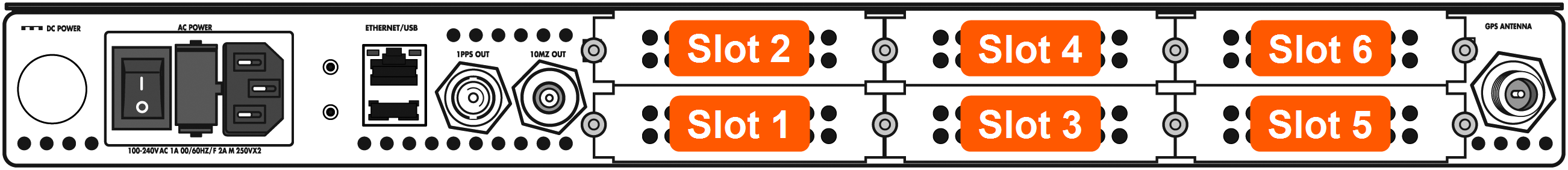
Unit rear view
Note: Follow only the PROCEDURE STEPS [x] listed for your option card and installation scenario!
Installation steps
| Part No. Option Card | Card Function | Installation Location |
Bottom Slot | PROCEDURE STEPS [x] |
|---|---|---|---|---|
| 1204-08 1204-26 1204-1C 1204-0C |
Frequency output | Slot 2, 4, or 6 | empty | (1), 2, 3, 5, 7, 11, (12) |
| populated | (1), 2, 3, 6, 7, 11, (12) | |||
| Slot 1, 3, or 5 | (1), 2, 3, 4, 7, 11, (12) | |||
| 1204-0F | Alarm relay | Slot 2, 4, or 6 | empty | (1), 2, 3, 5, 7, 10, 11, (12) |
| populated | (1), 2, 3, 6, 7, 10, 11, (12) | |||
| Slot 1, 3, or 5 | (1), 2, 3, 4, 7, 10, 11, (12) | |||
| 1204-06 | Gigabit Ethernet | Slot 2 | empty | (1), 2, 3, 8, 11, (12) |
| populated | (1), 2, 3, 9, 11, (12) | |||
| All other Part No.'s | (miscellaneous) | Slot 2, 4, or 6 | empty | (1), 2, 3, 5, 11, (12) |
| populated | (1), 2, 3, 6, 11, (12) | |||
| Slot 1, 3, or 5 | (1), 2, 3, 4, 11, (12) | |||