+1.585.321.5800
IRIG Out [1204-15, -1E, -22]
These IRIG Output option cards provide SecureSync with four IRIG outputs. Available with BNC connectors, Fiber Optic ST connectors, or RS-485 terminal block.
IRIG Out (BNC): Specifications
- Inputs/Outputs: (4) IRIG Outputs
- Output Signal: IRIG A, B, E, G, H, or NASA-36, amplitude modulated sine wave (AM), 0.5V to 6Vp-p into 50 Ω; or pulse-width-coded (DCLS).User-selectable.
- AM Carrier: IRIG B 1000 Hz, IRIG A and G 100 or 100
- AM Signal Level: 500 mV to 10 Vp-p [high Z]; (modulated 2:1 to 6:1).
- DCLS Signal Level: >10 kΩ TTL
- Connector: AM and DCLS: BNC female
- Accuracy: see IRIG Output Accuracy Specifications
- Number of Cards: Up to 6
- Ordering Information: 1204-15, IRIG module, BNC Connector
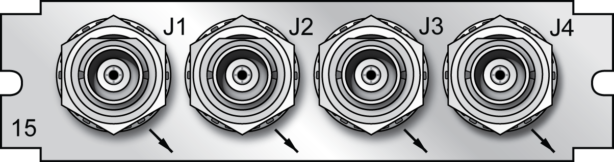
Model 1204-15 option card rear plate
IRIG Out (Fiber Optic): Specifications
- Inputs/Outputs: (4) IRIG Outputs
- Signal: IRIG A, B, E, G or NASA-36
- Operating Wavelength: 820/850 nm
- Optical Power: -15 dBm average into 50/125 fiber
- Fiber Optic Compatibility: 50/125 μm, 62.5/125 μm multi-mode cable
- Optical Connector: ST
- Signal Type: DC Level Shift (unmodulated)
- Accuracy: see IRIG Output Accuracy Specifications
- Maximum Number of Cards: 6
- Ordering Information: 1204-1E Four IRIG Output Module, Fiber Optic
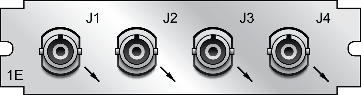
Model 1204-1E option card rear plate
IRIG Out (RS-485): Specifications
- Inputs/Outputs: (4) IRIG Outputs
- Signal: IRIG A, B, E, G or NASA-36
- Signal Type and Connector: RS-485 levels (terminal block)
- Output Load Impedance: 120 Ω
- Accuracy: see IRIG Output Accuracy Specifications
- Maximum Number of Cards: 6
- Ordering Information: 1204-22 Four IRIG Output Module, RS-485
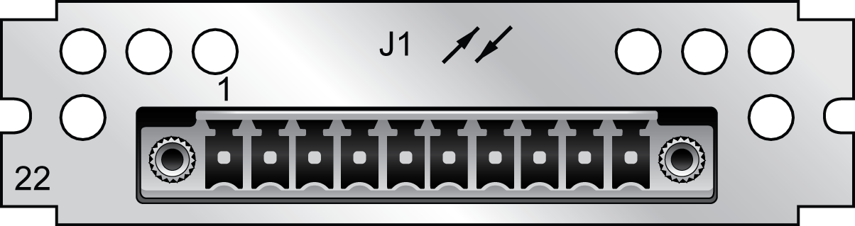
Model 1204-22 option card rear plate
Pin Assignments
| J1 Pin No. | Function |
|---|---|
| 1 | IRIG Output 1 + |
| 2 | IRIG Output 1 – |
| 3 | GND |
| 4 | IRIG Output 2 + |
| 5 | IRIG Output 2 – |
| 6 | IRIG Output 3 + |
| 7 | IRIG Output 3 – |
| 8 | GND |
| 9 | IRIG Output 4 + |
| 10 | IRIG Output 4 – |
1204-22 terminal block pin-out
IRIG Output: Viewing Signal State
To quickly view if an IRIG output is enabled or disabled, go to the option card’s Status Summary panel. For instructions, see: Viewing an Input/Output Signal State.
IRIG Output: Edit Window
To configure an IRIG Output, go to its Edit window. For instructions, see: Configuring Option Card Inputs/Outputs.
The Web UI list entries for these option cards are: IRIG Out BNC, IRIG Out Fiber, IRIG Out RS-485.
Note: SecureSync starts numbering I/O ports with 0 (only 1PPS and 10 MHz outputs start at 1, because of the built-in outputs).
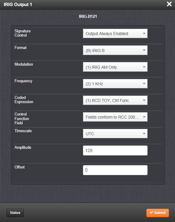
The Edit window allows the configuration of the following settings:
- Signature Control: Used to control when the IRIG modulation will be present. This function allows the modulation to stop under certain conditions; see also Signature Control.
- Format: Used to configure the desired IRIG output formatting. The available choices are:
- IRIG A
- IRIG B
- IRIG G
- IRIG E
- NASA-36
- Modulation: Changes the type of output signal modulation. The available choices are:
- IRIG DCLS: TTL-modulated output
- IRIG AM: Amplitude-modulated output. The amplitude of the output is determined by the value entered in the Amplitude field.
- Frequency: The IRIG modulation frequency. This is determined by the configuration of Format and Modulation Type. See IRIG Carrier Frequencies for details.
- Coded Expression: Defines the data structure of the IRIG signal, where:
- BCD = Binary Coded Decimal
- TOY = Time of Year
- CF = Control Field
- SBS = Straight Binary Seconds
Note: The available options will vary according to the values of Format and Modulation Type.
- Control Function Field: IRIG signals have an optional section in the data stream that can be used to include additional information (such as the present year, for example). This field allows the Control Field section of the IRIG output to be defined. The available configurations are:
- Fields conform to RCC 200-04: IRIG spec 200-04 specified a location for year value, if included in this field.
- Fields conform to IEEC 37.118-2005 (IEEE 1344): Control Field contains year, leap second and daylight savings time information.
- Fields conform to Spectracom Format: Year is included in Control Field but not in the same location as RCC-2004 output (year is offset by one position).
- Fields conform to Spectracom FAA Format: A unique IRIG output Control Field that contains satellite lock status and time error flags.
- Fields conform to NASA Formats: Variants of IRIG B
- Fields confirm to Spectracom IEEE C37.118-2005: Has been extended to support one-month leap second notification
Note: The available options will vary according to the configurations of Format and Modulation Type.
- Timescale: Used to select the time base for the incoming time code data. The entered Timescale is used by the system to convert the time in the incoming data stream to UTC time for use by the System Time. The available choices are:
- UTC: Coordinated Universal Time ("temps universel coordonné"), also referred to as ZULU time
- TAI: Temps Atomique International
- GPS: The raw GPS time as transmitted by the GNSS satellites (as of -, this is 18 seconds ahead of UTC)
- A local clock set up through the Time Management Page: This option will appear under the name of the local clock you have set up. See for more information. Local timescale allows a Local Clock to apply a time offset for Time Zone and DST correction.
- Amplitude: The peak-to-peak output voltage level into a 600 Ω load is adjusted by entering a digital control value in this field. The level adjustment has no effect on TTL outputs, only on AM formats. The value of 128 will cause the Mark amplitude to be about 5Vp-p into high impedance. A value of 200 results in an output amplitude of about 9Vp-p into high impedance.
Note: These are nominal values only. Actual values will vary from unit to unit. To adjust the level precisely, connect an oscilloscope to the output connector when adjusting.
- Offset: Provides the ability to account for IRIG cable delays or other latencies in the IRIG input. The Offset value is entered and displayed in nanoseconds (ns). The available Offset range is -500 to +500 ms.
For IRIG frequency and output specifications, see IRIG Standards and Specifications.
For information on IRIG output resolution, see About the IRIG Output Resolution.
IRIG Output: Status Window
To view the specifications of an IRIG Output, go to its Status window. For instructions, see: Viewing Input/Output Configuration Settings.
The Web UI list entries for these option cards are: IRIG Out BNC, IRIG Out Fiber, IRIG Out RS-485.
Note: SecureSync starts numbering I/O ports with 0 (only 1PPS and 10 MHz outputs start at 1, because of the built-in outputs).
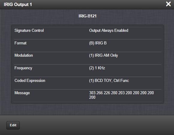
Descriptions of the settings shown in the Status window can be found IRIG Output: Edit Window. For IRIG frequency and output specifications, see IRIG Standards and Specifications.