+1.585.321.5800
1PPS In/Out [1204-28, -2A]
These 1PPS input/output cards provide one 1PPS input, and three or two additional 1PPS outputs on BNC or ST connectors for the SecureSync platform.
Model 1204-28 1PPS Input/Output: Specifications
- Inputs/Outputs: (1) 1PPS input/(3) 1PPS output
- Signal Type and Connector: TTL (BNC)
- Input Impedance: 50 Ω
- Output Load Impedance: 50 Ω
- Rise Time to 90% of Level: <10 ns
- Programmable Pulse Width: 100 ns to 900 ms with 20 ns resolution
- Absolute Phase Error: ±50 ns (1σ)
- Programmable Phase Shift: ±5ns to 500 ms with 5ns resolution
- Maximum Number of Cards: 6
- Ordering Information: 1204-28: 1PPS 1-input/3-output, BNC connectors
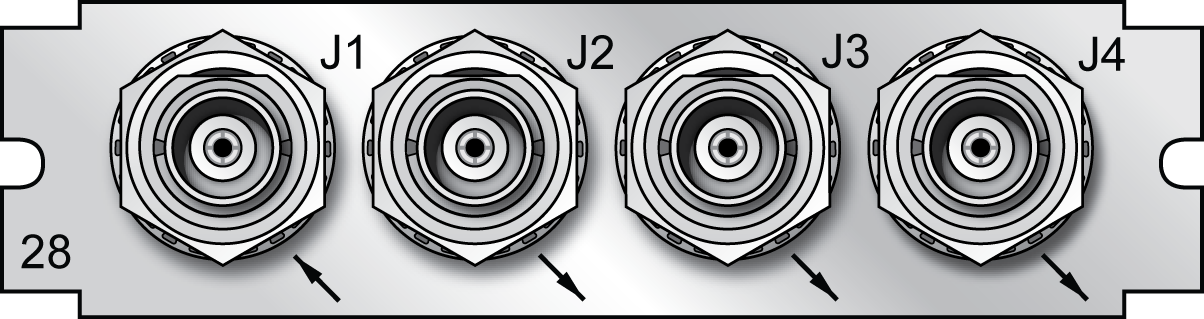
Model 1204-28 option card rear plate
Model 1204-2A 1PPS Input/Output: Specifications
- Inputs/Outputs: (1) 1PPS input/(2) 1PPS output
- Operating Wavelength: 820/850 nm
- Optical Input Minimum Sensitivity: -25 dBm @ 820 nanometers
- Optical Output Power: -15 dBm average into 50/125 fiber
- Fiber Optic Compatibility: 50/125 μm, 62.5/125 μm multi-mode cable
- Optical Connector: ST
- Output Programmable Pulse Width: 100 ns to 900 ms with 20 ns resolution
- Output Absolute Phase Error: ±50 ns (1σ)
- Output Programmable Phase Shift: ±5ns to 500 ms with 5ns resolution
- Maximum Number of Cards: 6
- Ordering Information: 1204-2A: 1PPS 1-in/2-output, ST connectors
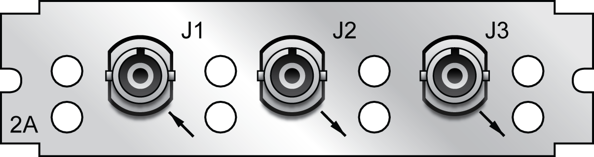
Model 1204-2A option card rear plate
1PPS Input or Output: Viewing Signal State
To quickly view if the 1PPS inputs and outputs of this option card are currently enabled or disabled, go to the option card’s Status Summary panel. For instructions, see: Viewing an Input/Output Signal State.
1PPS Output: Edit Window
To configure the settings of a 1PPS output, go to its Edit window. For instructions, see: Configuring Option Card Inputs/Outputs.
The Web UI list entries for these cards are:
- 1PPS In/Out
- 1PPS In/Out, Fiber
The connector numbers are:
- J2, J3, J4 (model -28)
- J2, J3 (model -2A)
Note: SecureSync starts numbering I/O ports with 0 (only 1PPS and 10 MHz outputs start at 1, because of the built-in outputs).
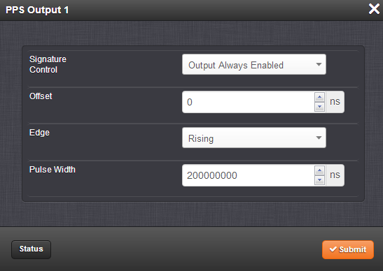
The fields available are:
- Signature Control: Used to control when the 1PPS output signal will be present. See: Signature Control.
- Offset: Used to account for 1PPS cable delays or other latencies in the 1PPS output. The Offset value is entered and displayed in nanoseconds (ns). The available Offset range is -500 to +500 ms.
- Edge: The operator can select if the output signal is a positive (reference on the rising edge) or a negative (reference on the falling edge) pulse.
- Pulse Width: Configures the Pulse Width of the 1PPS output. The Pulse Width is entered and displayed in nanoseconds (ns). The default Pulse Width is 200 milliseconds.
1PPS Output: Status Window
To view the current settings of a 1PPS output, go to its Status window. For instructions, see: Viewing Input/Output Configuration Settings.
The Web UI list entries for these cards are:
- 1PPS In/Out
- 1PPS In/Out, Fiber
The connector numbers are:
- J2, J3, J4 (model -28)
- J2, J3 (model -2A)
Note: SecureSync starts numbering I/O ports with 0 (only 1PPS and 10 MHz outputs start at 1, because of the built-in outputs).
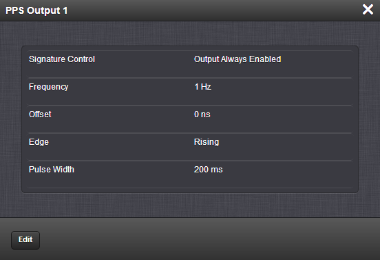
The fields displayed are:
- Signature Control: Displays the current configuration of Signature Control. See Signature Control.
- Frequency: Indicates the configured frequency of the 1PPS output signal.
- Offset: Displays the configured Offset (to account for cable delays or other latencies).
- Edge: Shows if the on-time point of the 1PPS output is the rising or falling edge of the pulse.
- Pulse Width: Displays the configured Pulse Width of the 1PPS output. The Pulse Width is displayed in nanoseconds (ns). The default Pulse Width is 200 milliseconds.
1PPS Input: Edit Window
To configure the settings of the PPS Input (also referred to as ‘Reference’), go to its Edit window. For instructions, see: Configuring Option Card Inputs/Outputs.
The Web UI list entries for these cards are:
- 1PPS In/Out
- 1PPS In/Out, Fiber
The connector number for the input is: J1
Note: SecureSync starts numbering I/O ports with 0 (only 1PPS and 10 MHz outputs start at 1, because of the built-in outputs).
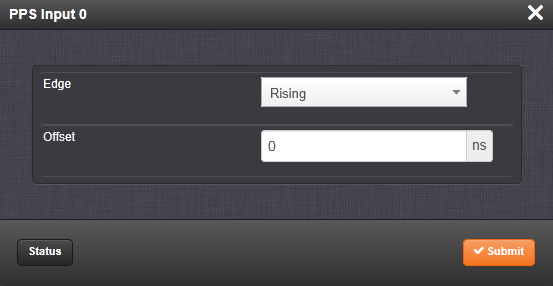
The Edit window allows the configuration of the following settings:
- Edge: The operator can select either the rising or the falling edge as the input time reference (defines the on-time point of the signal).
- Offset: It is possible to add an offset to the input signal (to account for cable delays), with a resolution of 5ns and a positive or negative value of 500 ms maximum.
1PPS Input: Status Window
To view the current settings of the PPS Input (also referred to as ‘Reference’), go to its Status window. For instructions, see: Viewing Input/Output Configuration Settings.
The Web UI list entries for these cards are:
- 1PPS In/Out
- 1PPS In/Out, Fiber
The connector number for the input is: J1
Note: SecureSync starts numbering I/O ports with 0 (only 1PPS and 10 MHz outputs start at 1, because of the built-in outputs). .
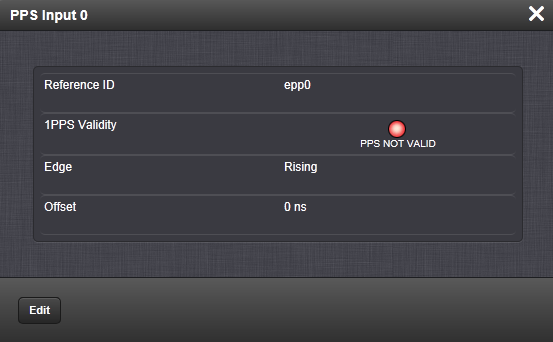
The Status window displays the following settings:
- Reference ID: Name used to represent this 1PPS input reference in the Reference Priority table. See also: Configuring Input Reference Priorities.
- 1PPS Validity: Indicates “OK” (green) if the 1PPS input signal is present and valid. Indicates “Not Valid” (orange) if the 1PPS input signal is either not present or is not considered valid.
- Edge: Displays the selected Edge (rising of falling) of the 1PPS input that defines the on-time point.
- Offset: Displays the configured 1PPS offset values.
The 1PPS Input signal is analyzed and an absence of the signal triggers a “Not Valid” indication.