+1.585.321.5800
STANAG In [1204-1D, -24]
The STANAG Input option cards 1204-1D and 1204-24 STANAG provide (2) configurable STANAG inputs and (1) 1PPS input for the SecureSync platform.
STANAG In [1204-1D, -24]: Specifications
- Inputs: (2) STANAG Inputs, (1) 1PPS Input
- Signal Type and Connector: TTL or RS-485 level (user selectable) for STANAG and 1PPS input. DB25.
- Formats Supported:
- STANAG 4246 HAVE QUICK I
- STANAG 4246 HAVE QUICK II
- STANAG 4372 HAVE QUICK IIA
- STANAG 4430 Extended HAVE QUICK
- STANAG 4430 Standard Time Message (STM)
- ICD-GPS-060A BCD Time Code
- ICD-GPS-060A HAVE QUICK
- DOD-STD-1399 BCD Time Code
- Accuracy: 100 ns
- Maximum Number of Cards: 6
- Ordering Information: 1204-1D (for non-isolated board); 1204-24 (for isolated board)

Model 1204-1D option card rear plate

Model 1204-24 option card rear plate
Pin Assignments
| Pin No. | Signal | Function | Pin No. | Signal | Function |
|---|---|---|---|---|---|
| 1 | GND | Ground | 14 | TOD1- | TOD1 RS-485- Input |
| 2 | TOD1+ | TOD1 RS-485+ Input | 15 | NC | - |
| 3 | NC | - | 16 | NC | - |
| 4 | TOD2+ | TOD2 RS-485+ Input | 17 | TOD2- | TOD2 RS-485- Input |
| 5 | NC | - | 18 | NC | - |
| 6 | GND | Ground | 19 | NC | - |
| 7 | GND | Ground | 20 | NC | - |
| 8 | NC | - | 21 | 1PPS- | 1PPS RS-485- Input |
| 9 | 1PPS+ | 1PPS RS-485+ Input | 22 | NC | - |
| 10 | TFD | Time Fault Discrete | 23 | GND | Ground |
| 11 | TOD1 | TOD1 TTL Input | 24 | 1PPS | 1PPS TTL Input |
| 12 | GND | Ground | 25 | GND | Ground |
| 13 | TOD2 | TOD2 TTL Input |
1204-1D, 1204-24 option cards: DB-25 pin-outs
STANAG Input: Edit Window
To configure a STANAG Input (also referred to as ‘Reference’), go to its Edit window. For instructions, see: Configuring Option Card Inputs/Outputs.
The Web UI list entries for this card are: STANAG In and STANAG In, Isolated.
The inputs are named: Stanag HQ Input [number].
Note: SecureSync starts numbering I/O ports with 0 (only 1PPS and 10 MHz outputs start at 1, because of the built-in outputs). .
The configurable settings are grouped under the following three tabs:
General Settings tab
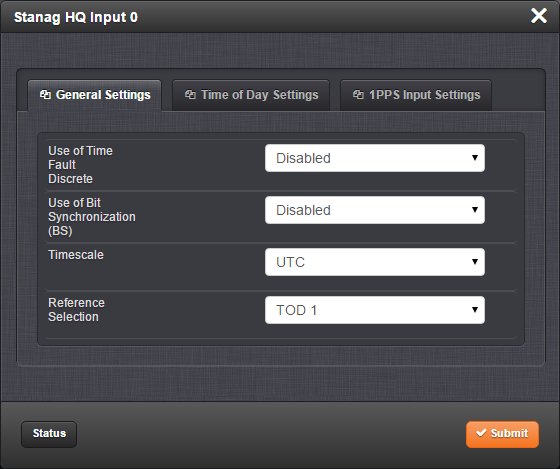
- Use of Time Fault Discrete: There are two options:
- Enabled: The TFD input signal is used to validate the STANAG input.
- Disabled (default): The TFD input signal is ignored.
- Use of Bit Synchronization (BS): There are two options:
- Enabled: The second STANAG input (TOD 2) is used to receive the BS (Bit Stream) signal used with STANAG 4430-STM. When BS is active, the configuration of TOD2 is superseded and only used for BS.
- Disabled: The second STANAG input (TOD 2) can be used to receive an independent TOD.
- Timescale: Used to select the time base for the incoming time code data. The entered Timescale is used by the system to convert the time in the incoming data stream to UTC time for use by the System Time. The available choices are:
- UTC: Coordinated Universal Time ("temps universel coordonné"), also referred to as ZULU time
- TAI: Temps Atomique International
- GPS: The raw GPS time as transmitted by the GNSS satellites (as of -, this is 18 seconds ahead of UTC time).
- A local clock set up through the Time Management Page: Refer to The Time Management Screen for more information on how to configure and read the System Time. Local timescale allows a Local Clock to apply a time offset for Time Zone and DST correction.
The incoming input time information may be provided as local time, but System Time may be configured as UTC time, so internal computations need to be performed. With the Timescale field set to “Local”, select the name of a previously created Local Clock. The Time Zone and DST rules, as configured in the Local Clock will be applied to the front panel time display. Refer to for more information on Local Clocks.
- Reference Selection: Selects TOD 1 or TOD 2 (configured below) which TOD signal is used for synchronization.
Time of Day Settings tab
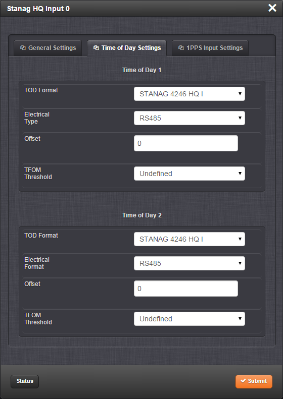
For Time of Day 1 and Time of Day 2 (STANAG content supports two ToD streams).
- ToD Format: The user-selectable format to be used. Available formats include:
- STANAG 4246 HAVE QUICK I
- STANAG 4246 HAVE QUICK II
- STANAG 4372 HAVE QUICK IIA
- STANAG 4430 Extended HAVE QUICK
- STANAG 4430 Standard Time Message (STM)
- ICD-GPS-060A BCD Time Code
- ICD-GPS-060A HAVE QUICK
- DOD-STD-1399 BCD Time Code
- Electrical Type: Selects synchronization to either RS-485 or TTL (supporting up to 10 V levels) signal lines.
- Offset: Provides the ability to account for STANAG Line (TOD1 and TOD2 independently) cable delays or other latencies in the STANAG input. Available Offset range is –500 to +500 ms in 5ns steps.
- TFOM Threshold: Under the STANAG protocol, the TFOM (Time Figure of Merit) threshold value can be utilized as a means to validate timing data based on the TFOM. For more information on TFOM, see Configuring the Oscillator.
1PPS Input Settings tab
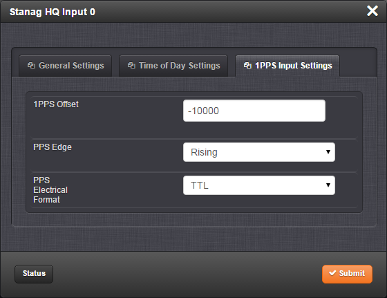
- 1PPS Offset: Used to account for 1PPS cable delays or other latencies in the 1PPS input. Available Offset range is –500 to +500 ms in 5ns steps
- PPS Edge: The operator can select if the output signal is a rising or falling edge pulse.
- PPS Electrical Format: Selects synchronization to either RS-485 or TTL (supporting up to 10 V levels) signal lines.
STANAG Input: Status Window
To view the current settings of a STANAG Input (also referred to as ‘Reference’), go to its Status window. For instructions, see: Viewing Input/Output Configuration Settings.
The Web UI list entries for this card are: STANAG In and STANAG In, Isolated.
The inputs are named: Stanag HQ Input [number].
Note: SecureSync starts numbering I/O ports with 0 (only 1PPS and 10 MHz outputs start at 1, because of the built-in outputs). .
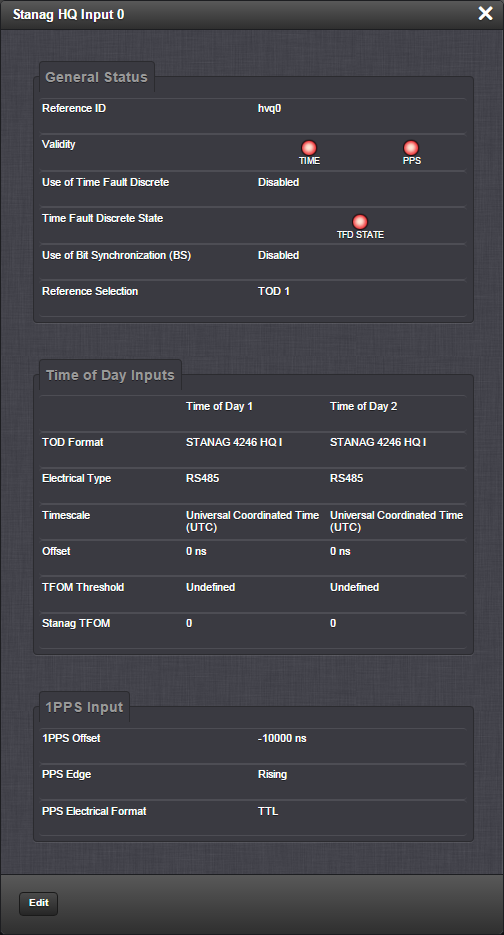
The Status window displays the following settings:
Under General Status:
- Reference ID: This is the identifier given to the input by SecureSync.
- Validity: Indicates the validity of the Time input and the PPS input. If the input signal is valid the indicator will be green. If the signal is not valid, the indicator will be orange.
- Use of Time Fault Discrete: There are two options:
- Enabled: The TFD input signal is used to validate the STANAG input.
- Disabled (default): The TFD input signal is ignored.
- Time Fault Discrete State: If this is valid, the indicator will be green. If it is not valid, the indicator will be orange.
- Use of Bit Synchronization (BS): There are two options:
- Enabled: The second STANAG input (TOD 2) is used to receive the BS (Bit Stream) signal used with STANAG 4430-STM. When BS is active, the configuration of TOD2 is superseded and only used for BS.
- Disabled: The second STANAG input (TOD 2) can be used to receive an independent TOD.
- Reference Selection: Indicates which TOD signal is used for synchronization. This will be either TOD 1 or TOD 2.
The incoming input time information may be provided as local time, but System Time may be configured as UTC time, so internal computations need to be performed. With the Timescale field set to “Local”, select the name of a previously created Local Clock. The Time Zone and DST rules, as configured in the Local Clock will be applied to the front panel time display. Refer to for more information on Local Clocks.
Under Time of Day Inputs:
- TOD Format: The user-selectable format being used. Available formats include:
- STANAG 4246 HAVE QUICK I
- STANAG 4246 HAVE QUICK II
- STANAG 4372 HAVE QUICK IIA
- STANAG 4430 Extended HAVE QUICK
- STANAG 4430 Standard Time Message (STM)
- ICD-GPS-060A BCD Time Code
- ICD-GPS-060A HAVE QUICK
- DOD-STD-1399 BCD Time Code
- Electrical Type: Either RS-485 or TTL (supporting up to 10 V levels) signal lines.
- Time Scale: Used to select the time base for the incoming time code data. The entered Timescale is used by the system to convert the time in the incoming data stream to UTC time for use by the System Time. The available choices are:
UTC: Coordinated Universal Time ("temps universel coordonné"), also referred to as ZULU time
TAI: Temps Atomique International
GPS: The raw GPS time as transmitted by the GNSS satellites (as of -, this is 18 seconds ahead of UTC time).
A local clock can be set up through the Time Management Page; see Local Clock(s), DST. Local timescale allows a Local Clock to apply a time offset for Time Zone and DST correction.
- Offset: Provides the ability to account for STANAG Line (TOD1 and TOD2 independently) cable delays or other latencies in the STANAG input. Available Offset range is –500 to +500 ms in 5ns steps.
- Stanag TFOM: The Time Figure of Merit for the input.
Under 1PPS Input:
- 1PPS Offset: Used to account for 1PPS cable delays or other latencies in the 1PPS input. The available Offset range is –500 to +500 ms in 5ns steps.
- PPS Edge: Indicates whether the output signal is a rising or falling edge pulse.
- PPS Electrical Format: Indicates whether the signal is synchronized to RS-485 or TTL (supporting up to 10 V levels) signal lines.