+1.585.321.5800
Unit Rear Panel
The SecureSync rear panel accommodates the connectors for all input and output references.
- Optional AC connection for the power input
- Optional DC power connector
- Ethernet and USB connections
- 1PPS output
- 10 MHz output
- Six bays for option cards
- One optional antenna connector.
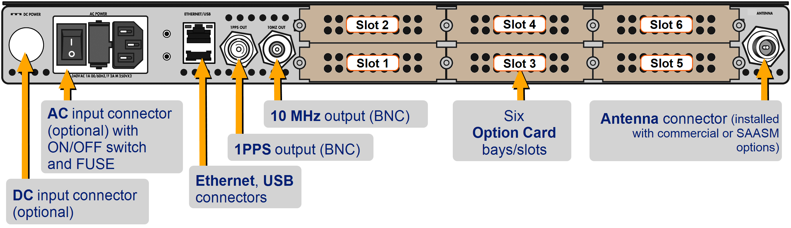
Standard rear panel
Typically, option cards will be installed at the factory.
The DC Power port connector is only installed if your unit was ordered with a DC input power option.
Note: DC input power does not have an ON/OFF switch.
- The AC Power connector is the input for the AC power and provides an AC power ON/OFF switch. This connector assembly is only installed if SecureSync was ordered with AC input power option.
- The Ethernet connector provides an interface to the network for NTP synchronization and to obtain access to the SecureSync product Web UI for system management. It has two small indicator lamps, “Good Link” (green LED), and “Activity” (orange LED).
Ethernet status indicator lights
| LED | State | Meaning |
|---|---|---|
| Orange | On Off |
LAN Activity detected No LAN traffic detected |
| Green | On Off |
LAN Link established, 10 or 100 Mbps No link established |
- The USB connector is reserved for future expansion.
- The 1PPS BNC connector offers a once-per-second square-wave output signal.
- The 10 MHz BNC connector provides a 10 MHz sine-wave output signal.
- The optional ANTENNA connector is a type “N” connector for the GNSS input from your GNSS antenna via a coax cable.