Connectors and their Pinouts
All of VersaSync's connectors are provided at the front panel of the unit, below the Status LEDs.
Power Connector
Note: View in mating direction from front.
Power connector pinout
| Pin | Signal |
|---|---|
| 1 | VMain (10 to 32 V) |
| 2 | -not used- |
| 3 | VStandby (10 to 32 V) |
| 4 | GND (to Standby) |
| 5 | GND (to Main) |
This product is designed to handle a maximum voltage of up to 32 VDC. Power supplies with higher voltage or transient/ cranking power will require a power conditioner or surge blocker.
Caution: Reversed polarity can blow an internal fuse that protects the product from damage. Use care when building power cables.
Test any new cables to safely power the unit before connecting your VersaSync to any other inputs or outputs (such as a GNSS antenna), and before grounding your unit to a vehicle.
Input/Output Connector
VersaSync has a 26-pin input/output connector that offers 8 software-configurable CHANNELS, plus one fixed DCLS channel, and a USB interface. To learn more about types of interfaces and signals, and how to configure them, see Assigning I/O Pins.
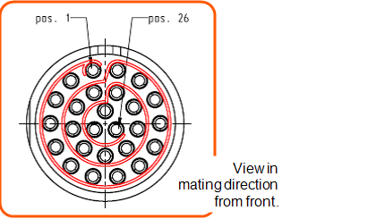
Default I/O connector pinout
| Pin | Channel | Signal | Pin | Channel | Signal |
|---|---|---|---|---|---|
| 1 | 0 | 1PPS output (5V) | 15 | 7 | Have Quick output (RS-485 signal +) |
| 2 | GND | 16 | GND | ||
| 3 | 1 | Have Quick input (RS-485 signal +) | 17 | 8 | Have Quick output (RS-485 signal –) |
| 4 | GND | 18 | GND | ||
| 5 | 2 | Have Quick input (RS-485 signal –) | 19 | 9 (USB dedicated) |
GND |
| 6 | GND | 20 | GND | ||
| 7 | 3 | 1PPS output (10 V) | 21 | Not connected | |
| 8 | GND | 22 | GND | ||
| 9 | 4 | ASCII output (RS-232) | 23 | USB D– | |
| 10 | GND | 24 | GND | ||
| 11 | 5 | 1PPS input | 25 | USB D+ | |
| 12 | GND | 26 | GND | ||
| 13 | 6 | ASCII input (RS-232) | |||
| 14 | GND | ||||
Ethernet Connector
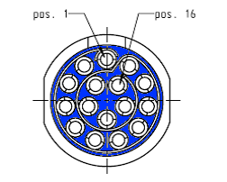
Note: View in mating direction from front.
The Ethernet connector provides two 1GbE network connections, using 8 wires (pinout below).
Ethernet connector pinout
| Pin | Signal | Pin | Signal |
|---|---|---|---|
| 1 | Ethernet_1 A+ | 9 | Ethernet_2 A+ |
| 2 | Ethernet_1 A– | 10 | Ethernet_2 A– |
| 3 | Ethernet_1 B+ | 11 | Ethernet_2 B+ |
| 4 | Ethernet_1 B– | 12 | Ethernet_2 B– |
| 5 | Ethernet_1 C+ | 13 | Ethernet_2 C+ |
| 6 | Ethernet_1 C– | 14 | Ethernet_2 C– |
| 7 | Ethernet_1 D+ | 15 | Ethernet_2 D+ |
| 8 | Ethernet_1 D– | 16 | Ethernet_2 D– |
It is also possible to wire your connector to 100MbE, using only 4 wires. Contact Tech Support for more information.
The pinouts described above are from the hardware design. They correspond with the software naming convention of interfaces as follows: Ethernet_1 is referred to as "eth0" in the system and Web UI, and Ethernet_2 is referred to as "eth1".
Optional I/O Connector
The Optional I/O connector ("SAASM" or "FILL/Z") is used in conjunction with the Option Board that is available for VersaSync. If the unit is not equipped with an Option Board, this connector is not used.
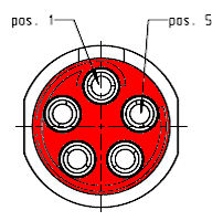
Coaxial Connectors
VersaSync offers five (5) coaxial connectors. Standard configuration includes the GNSS antenna input connector and (4) 10 MHz sinewave outputs. (Certain models may have variation on this setup. Refer to your purchase order for information on your VersaSync model.)
The coaxial connectors (aside from the GNSS connection) produce a 10MHz output that can be simultaneously disabled through the Web UI.
All coaxial connectors are standard SMA connectors (recommended torque value: 8-10 in-lbs).
Mating Connector Plugs
The table below lists the part numbers for the mating connectors. The connectors can be ordered through Orolia or ODU-USA Inc. All connectors are circular ODU AMC® "mil-type" connectors.
Connector Part Numbers
| Ref | Description | VersaSync Connector | Mating (Cable) Connector | ||
|---|---|---|---|---|---|
| Orolia Part No. | ODU Part No. | Orolia Part No. | ODU Part No. | ||
| POWER | Power connector, 5 pin | J240R-0051-002Q | GK1YBR-P05UJ00-000L | P240R-0051-002Q | S11YBR-P05XJG0-0000 |
| I/O | I/O connector, 26 pin | J240R-0261-002F | GK2YAR-P26UC00-000L | P240R-0261-002F | S12YAR-P26XCD0-0000 |
| ETH | Ethernet connector, 16 pin | J240R-0161-002F | GK1YCR-P16UC00-000L | P240R-0161-002F | S11YCR-P16XCD0-0000 |
|
SAASM, FILL/Z |
Optional I/O connector, 8 pin | J240R-0081-012F | GK1YDR-P08UF00-000L | P240R-0081-002F | S11YDR-P08XFG0-0000 |
ODU® ordering contact information (USA):
- ODU-USA Inc.
4010 Adolfo Road
Camarillo, CA 93012
United States of AmericaPhone: +1 (805) 484 0540
Fax: +1 (805) 484 7458
Email: sales@odu-usa.com
Note: Building the mating cables requires special tools. Contact ODU for cable assemblies. Be advised that typical lead times are 12 to 16 weeks.
ETHERNET connector wiring:
- 1 through 8: A Ethernet Connect, 4 pairs, 1000bT (in the software, eth0)
- 9 through 16: B Ethernet Connect, 4 pairs, 1000bT (in the software, eth1)
POWER connector pinout
- 1: VMain, 10 to 32 VDC
- 2: -not used-
- 3: VStandby, 10 to 32 VDC (Standby Power)
- 4: Ground return, standby power
- 5: Ground return, main power