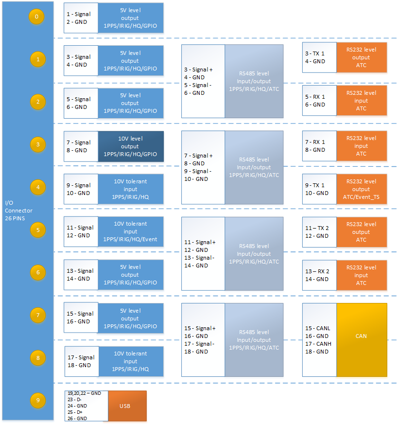
Assigning I/O Pins
VersaSync's I/O connector is software configurable, i.e. the pin interfaces and the signal modulations can be configured by the user via the VersaSync Web UI.
The software-configurable 26-pin I/O connector comprises 9 user-configurable Channels, plus one fixed USB interface. Channels can be used for the following input or output interfaces:
Signal Types
The table below shows the maximum number of available interfaces for each signal type. Note that you can assign only one signal for each pin pair, hence only four to nine input and output signals can be transmitted/received at any given time.
Available signal types
| DCLS, TTL | DCLS, 10V | RS485 | RS 485, 120 Ω | RS232 | |
|---|---|---|---|---|---|
| PPS | out (5), in (2) | out (1), in (1) | out (4), in (4) | in (4) | |
| IRIG | out (5), in (2) | out (1), in (1) | out (4), in (4) | in (4) | |
| HQ | out (5), in (2) | out (1), in (1) | out (4), in (4) | in (4) | |
| GPIO | out (5) | out (1) | |||
| ASCII | out (4), in (4) | in (4) | out (3), in (3) |
Note: ASCII Time Code is abbreviated in the UI as ATC.
DCLS Signal Lines
Up to six TTL (5V) or 10 V DCLS outputs and three DCLS inputs are available for e.g., 1PPS, xPPS, IRIG, HaveQuick, ASCII ToD signal transmission.
Single-ended Serial Lines
VersaSync provides up to 3 RX and 3 TX RS232 interfaces for e.g., ASCII..
Differential Serial Lines
Up to four differential serial lines are available. Each of them can be set to RS485 electrical standard, and used as input or output. PPS or Time-of-Day messages are available, as well as HAVE QUICK and other formats. Note that this kind of interface uses two Channels.
Non-Configurable Pins
Channel # 0 provides a DCLS TTL output signal that is not user-configurable.
Also note that pins # 19 through 26 are reserved for the USB command line interface.
I/O Signal Mapping Table
Each Channel (i.e., each pin pair e.g., "3&4" = Channel 1) can serve as only one interface, and not all combinations are possible due to the internal multiplexer architecture.
The table below illustrates the signal combinations that can be assigned to the 18 configurable pins.
I/O signal mapping to Channels
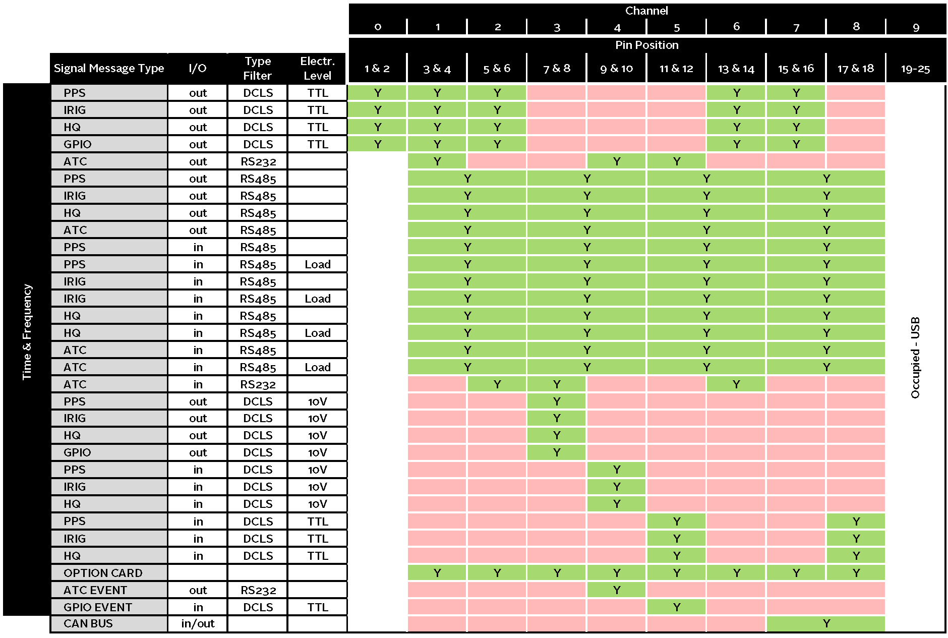
Notes:
Pins to Channels (e.g., pins 3 & 4= Channel 1)
green = Signal Message Type can be assigned to this Channel (RS485 requires two Channels)
red = This Signal Message type cannot be assigned to this Channel
ATC = ASCII Time Code
Interactive I/O Configurator
Each Channel can serve as only one interface, and not all combinations are possible due to the internal multiplexer architecture. Use the interactive I/O switch matrix below to design your I/O configuration by dragging any signal type from the left-hand column to one of the highlighted fields.
- In the VersaSync Web UI, navigate to MANAGEMENT > NETWORK: Pin Layout. The Pin Layout screen will be displayed.
- Prior to assigning the new output, identify a pin pair in the pin Layout table that is not used (Signal = "None") or not needed. You can Delete it, but you may also simply assign the new PPS Output as described below, thus overwriting the existing Input or Output.
- Add a pin configuration by clicking the PLUS icon in the top-right corner. The Add Pin window will display.
- Start with the Type Filter drop-down menu (second line in the window) and select a signal type.
- From the Signal drop-down menu, select a signal.
- From the Pins drop-down menu in line 3, select the pin pair you chose in Step 2. (Note that you will need 4 pins if you selected a RS485 signal Type.)
- Click Submit.
-
In the Actions panel, click Apply Changes.
VersaSync is shipped with a default I/O configuration that you can be customized. However, if required you can restore the default configuration at any time after applying changes.
The following illustration shows the default I/O pin configuration:

Default I/O configuration
To restore the default I/O pin configuration:
- Navigate to the MANAGEMENT: NETWORK > Pin Layout screen.
- In the Actions panel on the left, click Restore Default Layout.
To reload the currently used I/O configuration after adding pin layout changes, but before clicking Apply Changes:
- Navigate to the MANAGEMENT: NETWORK > Pin Layout screen.
- In the Actions panel on the left, click Reload Layout.