Configuring an ASCII Output
The ASCII outputs (ATC = ASCII Time Code) provide VersaSync with the ability to output one, two or three back-to-back ASCII time code data streams that can be provided to peripheral devices which accept an ASCII RS-232 or RS-485 input data stream for either their external time synchronization or for data processing. See Time Code Data Formats for a description of all supported time code formats.
The RX signal on an output interface is used for triggering the output ASCII message output when a configured character is received from the peripheral device.
When VersaSync is configured to output only one format message (the second and third formats configured as “None”), the one configured message will be available on the output port as either a broadcast message or only upon a request character being received. VersaSync has the ability to output one or two additional data stream messages immediately following the first message. In this configuration, only the first message determines the on-time point for the entire output string. The on-time points for the second and third messages that are provided at the same time as the first message are discarded. This unique capability allows VersaSync to be able to simultaneously provide multiple pieces of data from different selected format messages.
An example of selecting multiple formats is selecting “NMEA GGA” as the first format, “NMEA RMC” as the second format and “NMEA ZDA” as the third format. Depending on the setting of the “Mode” field (which determines if the data streams are available every second or upon a request character being received), at the next second or the receipt of the next request character, the output port will provide the GGA message followed immediately by the corresponding RMC message for that same second, followed immediately by the corresponding ZDA message for that same second. The first GGA message will provide the on-time point for the entire output data stream.
To configure an ASCII Output:
- Navigate to INTERFACES > OUTPUTS: ASCII Output 0, or to INTERFACES > OPTION CARDS: ASCII Output 0. The status window will display, providing information on Signature Control and the message format (s).
- Click the Edit button to open the configuration window:
- Format Group: configures the message format type. Choices are:
- None (no message will be output)
- Spectracom
- NMEA
- BBC
- ICD-153
- EndRun
Once selected, the Format Group may offer a choice of Formats. For more information on supported Formats, see Time Code Data Formats.
- Format 1: Selects either the first of up to three, or the only format message to be output.
- Format 2: Selects the second consecutive format message to be outputted. Select “None” if only one output format is desired. “None” will be the only choice available if Format 1 is “None.”
- Format 3: Selects the third consecutive format message to be outputted. Select “None” if only one output format is desired. “None” will be the only choice available if Format 2 is “None.”
- Signature Control: Signature Control controls when the selected ASCII data output format will be present; see Signature Control.
- Output Mode: This field determines when the output data will be provided. The available Mode selections are as follows:
- Broadcast: The format messages are automatically sent out on authorized condition (Signature control), every second a message is generated in sync with the 1PPS.
- Request (On-time): A format message is generated in sync with 1PPS after the configured request character has been received.
- Request (Immediate): A format message is generated as soon as the request character is received. As this selection does not correlate the output data to the on-time point for the message, in Data Formats that do not provide sub-second information (such as Formats 0 and 1 whereas Format 2 provides sub-second information), it should be noted that the output data can be provided immediately, but a time error could occur when using the on-time point of the message in addition to the data for timing applications.
Note: The choices available in this field are determined by the choices of Format Group and Format.
- Timescale: Used to select the time base for the incoming data. The entered Timescale is used by the system to convert the time in the incoming data stream to UTC time for use by the System Time. The available choices are:
- UTC: Coordinated Universal Time ("temps universel coordonné"), also referred to as ZULU time
- TAI: Temps Atomique International
- GPS: The raw GPS time as transmitted by the GNSS satellites (as of <D-M-Y>, this is currently 18 seconds ahead of UTC time).
If GPS or TAI time is used, then the proper timescale offsets must be set on the MANAGEMENT: OTHER > Time Management page. (See The Time Management Screen for more information on how to configure and read the System Time). Local timescale allows a Local Clock to apply a time offset for Time Zone and DST correction.
- A Local Clock can be set up through the Time Management page: This option will appear under the name of the local clock you have set up. See for more information. Local timescale allows a Local Clock to apply a time offset for Time Zone and DST correction.
The incoming input time information may be provided as local time, but System Time may be configured as UTC time, so internal computations need to be performed. With the Timescale field set to “Local”, select the name of a previously created Local Clock.
- Baud Rate: Determines the speed at which the output port will operate.
- Data Bits: Defines the number of Data Bits for the output port.
- Parity: Configures the parity checking of the output port.
- Stop Bits: Defines the number of Stop Bits for the output.
- Click Submit.
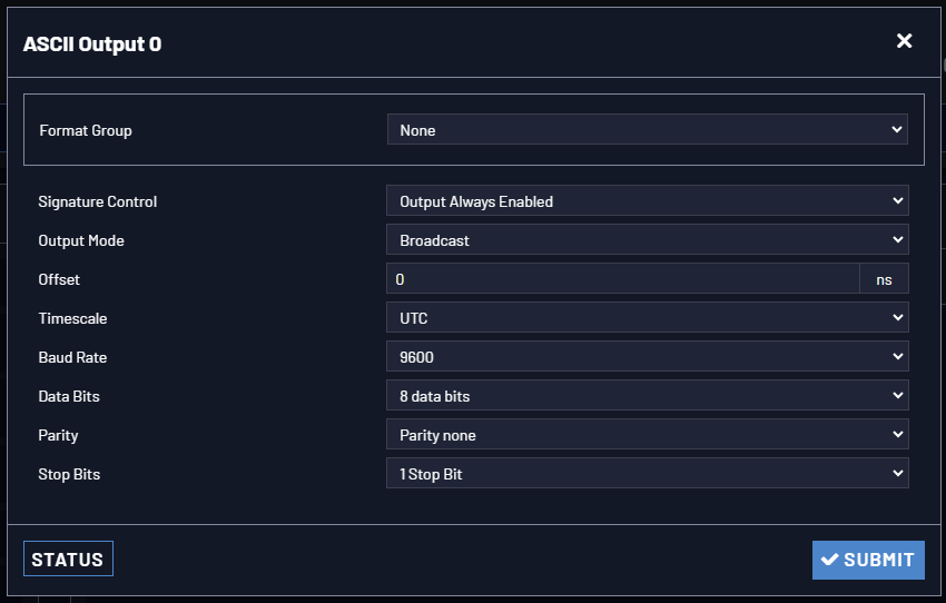
The Edit window allows the configuration of the following settings: