+1.585.321.5800
Alarm Relay Out [1204-0F]
The Model 1204-0F Alarm Relay Option Card provides three (3) configurable relay outputs for the SecureSync platform.
Alarm Relay Out [1204-0F]: Specifications
- Inputs/Outputs: (3) three contact relay connections (NC, common, NO)
- Signal Type and Connector: Terminal block
- Contacts switch under max. load of 30 VDC, 2A
- Contacts rated to switch: 220 VDC
- Nominal Switch Capacity: 30 V, 2A
- Maximum switch voltage: 220 VDC
- Maximum switch power: 60 W
- Maximum switch current: 2A
- Breakdown voltage: 1000 VDC between contacts
- Switch time: 4ms, max.
- Maximum Number of Cards: 1
- Ordering Information: 1204-0F: Relay Outputs Module

Model 1204-0F option card rear plate
Terminal block pin-out, alarm relay out
| PIN | SIGNAL |
|---|---|
| 1 | GND |
| 2 | Relay 0 NO |
| 3 | Relay 0 NC |
| 4 | Relay 0 COMMON |
| 5 | Relay 1 NO |
| 6 | Relay 1 NC |
| 7 | Relay 1 COMMON |
| 8 | Relay 2 NO |
| 9 | Relay 2 NC |
| 10 | Relay 2 COMMON |
Contact closure relay pinouts
- All relay contacts are labeled as in their de-energized state (power removed or alarm asserted).
- The "normal" state of the relays (no alarms asserted) is relays energized.
- The applicable relay(s) (Minor or Major, as configured in the browser) is /are de-energized when a Minor or Major alarm is asserted.
- Both the Minor and Major alarms are active (relays de-energized and in their alarm state) when input power is removed from SecureSync.
- For information on how to configure the relays as either a Minor alarm relay or a Major alarm relay, see Alarm Relay Output: Edit Window.
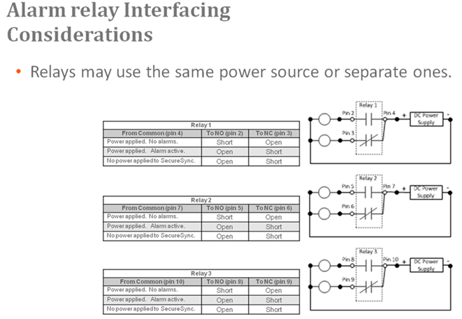
Each of the three available relays on this option card can be configured to be either a Minor or a Major alarm relay. The three relays are dry contact closures that can either open or complete a circuit, depending on whether the relay is energized/de-energized and whether the custom alarm circuit is connected to the NO or NC contacts.
To use this option card to provide an audible indication of a Minor or Major alarm being asserted, SecureSync does not pass or generate an audible tone. It is just the switch that allows the tone to be generated. Or for a visible alarm indication, the three relays can allow DC voltage to be routed to the light, when an alarm is asserted.
The best way to think of each of the alarm relays is that they are simply a light switch on the wall. When the switch is off (relay is in one position) the light/buzzer is off. But if you toggle the switch (relay) to the other position (either a Minor or Major alarm is alarm is asserted), the light/buzzer comes on. When a Minor or Major Alarm is asserted, the applicable relay(s) switches states. This can then allow a custom circuit to be able to sound an alarm or to illuminate a light, as desired.
The nominal switch capacity is 30V, 2A (maximums: voltage = 220 VDC, power = 60W, current = 2A). So you can connect any desired audible//visible device or component to this relay that can operate within this rating (Spectracom doesn't make any specific recommendations on what visible or audible alarms to use in conjunction with this Option Card). Further below is a diagram of ways that a light or buzzer can be connected to any of the three relays on this Option Card.
Note that any necessary wiring, the light/buzzer and the power source (labeled in the diagram above as “DC Power Supply”) for the light/buzzer is supplied by the customer. “Relay 1”, “Relay 2” and “Relay 3” represent the three available relays. The three tables on the left provide the pin-outs for each of the relay contact closures.
Alarm Relay Output: Viewing Signal State
To quickly view the signal state of all three alarm outputs, see: Viewing an Input/Output Signal State.
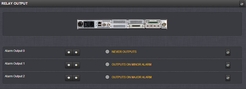
Each alarm output will be in one of these 3 states:
- NEVER OUTPUTS
- OUTPUTS ON MINOR ALARM
- OUTPUTS ON MAJOR ALARM
Alarm Relay Output: Edit Window
To configure the Alarm Relay Output, go to its Edit window. For instructions, see: Configuring Option Card Inputs/Outputs.
The Web UI list entry for this card is: Relay Output. The name of the output is: Alarm Output [number].
Note: SecureSync starts numbering I/O ports with 0 (only 1PPS and 10 MHz outputs start at 1, because of the built-in outputs).
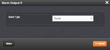
The Edit window allows the configuration of the following settings:
- Alarm Type:
- None: Will not output for an alarm.
- Minor: Will output on a minor alarm.
- Major: Will output on a major alarm.
Alarm Relay Output: Status Window
To view the current settings of an Alarm Relay Output, go to its Status window. For instructions, see: Viewing Input/Output Configuration Settings.
The Web UI list entry for this card is: Relay Output. The name of the output is: Alarm Output [number].
Note: SecureSync starts numbering I/O ports with 0 (only 1PPS and 10 MHz outputs start at 1, because of the built-in outputs).
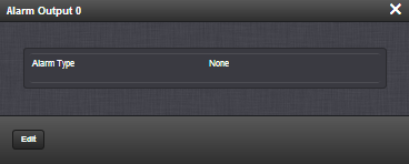
The Status window displays the following settings:
- Alarm Type:
- None: Will not output for an alarm.
- Minor: Will output on a minor alarm.
- Major: Will output on a major alarm.