+1.585.321.5800
Scenario Execution Views
While a scenario is running (also referred to as "scenario execution"), you can display several views, so as to …
- monitor the current scenario status
- verify the operation of your receiver-under-test by comparing its output with the data provided in the scenario execution views
- adjust some of the scenario settings.
Views displayed during scenario execution
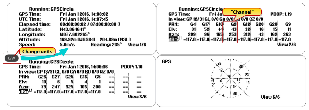
To display the views in successive order, press the view key. In the lower right corner e.g., View 2/6 may be displayed, indicating the current view/total number of views. The total number, and content of views depends on the number of signals used in the scenario.
Note: When you press the exit key to leave a menu, its settings will be taken into use immediately, and all band- or satellite-specific offsets are discarded.
See Running a Scenario to find out how you can interact with the system during scenario execution, and to learn which scenario settings can be adjusted.
View 1/x
View 1/x displays the scenario name, and information about the simulation GPS date and time, current position, speed and direction, and elapsed time.
View >1/x
Views >1/x display information pertaining to the individual simulated satellites. Up to 8 channels are shown per view (the maximum number of channels is 64, depending on your GSG model, and configuration).
The first line repeats the …
- … GPS date and time (as in View 1/x), and displays the …
- … HDoP (Horizontal Dilution of Precision): A dimensionless number indicating the relative quality of the calculated horizontal position, which is largely a function of the current satellite constellation. [A smaller number is better; the number will never be 0 or 2.]
The remaining lines are:
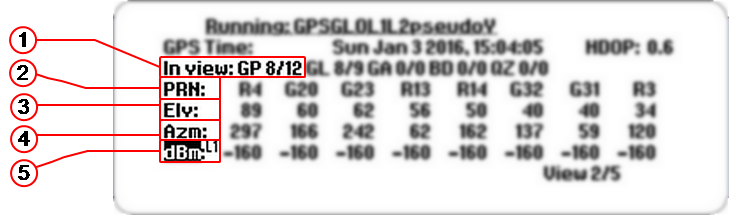
 In view: Shows the abbreviation of each satellite system, followed by its number of satellites in view/GSG channels reserved. Satellite system abbreviations are:
- PRN: Pseudo-Range Number (satellite identifier). The identifiers are:
Letters are lower case if a satellite is unhealthy, or if the ephemeris data is too old to be used.
For multipath replicas, the letter 'D' will be displayed next to the satellite number.
Fading satellite signals are indicated by the letter ‘F’ (see end of Chapter Propagation Environment Models for more information).
- iUG, for unmodulated GPS interference signal
- iUE, for unmodulated Galileo interference signal
- iUC, for unmodulated BeiDou interference signal
- iUJ, for unmodulated QZSS interference signal
- iUx, for unmodulated GLONASS interference signal, where ‘x’ is the frequency slot ranging from -7 to 6
- iSg, for sweeping GPS interference
- iSr, for sweeping Glonass interference
- iSe, for sweeping Galileo interference
- iSc, for sweeping BeiDou interference
- iSj, for sweeping QZSS interference
- iNg, for noise GPS interference
- iNr, for noise Glonass interference
- iNe, for noise Galileo interference
- iNc, for noise BeiDou interference
- iNj, for noise QZSS interference
- ELV: Satellite elevation
- AZM: Azimuth
- dBM: decibel Milliwatt
Interference signals are recognized by their elevation and azimuth fields since these will be marked as *.
Furthermore, when the interference signal is un-modulated this is identified by a CG for GPS interference signals and a leading C letter followed by the frequency slot number for GLONASS interference signals.
Hence, next to the identifiers listed above, the following identifiers may also be displayed:
Example
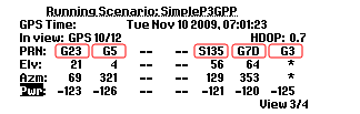
The example above illustrates two GPS signals (G23 and G5), one SBAS signal (S135), one multipath signal (G7D) and one interference signal (G3).
Last View
The last view (e.g. View 4/4) shows a skyplot, illustrating how the simulated satellites are located in the sky.
Press the LEFT/RIGHT arrow keys to scroll through the skyplots, if more than 2 constellations are simulated.
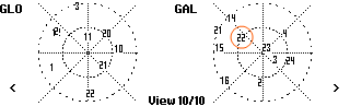
The center of the plot represents the current receiver position, and the outermost circle the horizon, i.e. the elevation of a satellite located near this circle is low. The lines represent the azimuth (North = 0°). For example, in the GALileo plot shown above, satellite number 22 would have an elevation of approximately 45°, and an azimuth near 300°.